17
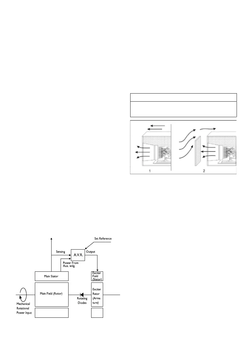
the automatic voltage regulator (see Figure 13.1) The
process begins when the engine starts to rotate the in
-
ternal components of the alternator. The residual mag-
netism in the main rotor produces a small alternating
voltage (AQ in the main stator. The automatic voltage
regulator recties this voltage (converts it to DC) and
applies it to the exciter stator.
This DC arrent to the exciter stator creates a magnetic
eld which in turn, induces an AC voltage in the exciter
rotor. This AC voltage is converted back to DC by the
rotating diodes.
When this DC voltage appears at the main rotor, a
stronger magnetic eld than the original residual eld
is created which induces a higher voltage in the main
stator. This higher voltage circulates through the system
indudng an even higher DC voltage back at the main
rotor. This cycle continuous to build up the voltage unit.
It approaches the proper output level of the genera
-
ting set. At this point the automatic voltage regulator
begins to limit the voltage being passed to the exciter
stator which, in turn, limits the overall power output of
the alternator.
This build-up process takes place in less than one se
-
cond.
13.4. Automatic Voltage Regulator
The Automatic Voltage Regulator (AVR) maintains a no
load to il load steady state voltage to tight tolerances.
The AVR has a volt/herz characteristic which proporti
-
onally reduces the regulated voltage at reduced.
Figure, 13,1. Meccalte alternator, operating principles
block schematic diagram
14. VENTS AND DUCTS
1. For indoor installations, locate vents so incoming air
passes through the immediate area of the installation
before exhausting. Install the air outlet higher than the
air inlet to allow for convection air movement.
2. Size the vents and ducts so they are large enough to
allow the required ow rate of air.
3. Wind will restrict free airow if it blows directly into
the air outlet vent. Locate the outlet vent so the effects
of wind are eliminated, or if the outlet vent cannot be
located as mentioned, install a wind barrier. See Figure 8
No.1 : Prevailing Wind Away from Air Outlet Vent
No.2 : Prevailing Wind Towards Air Outlet Vent,
Wind Barrier Installed
Fig.12.1. Wind Barrier
NOTICE
The “free area” of ducts must be as large as the exposed
area of the radiator. Refer to the generator set Speci
-
cation Sheet for the airow requirements and allowed
airow restriction.