Do you have a question about the Akuvox A02 and is the answer not in the manual?
Details the steps for mounting the device to a wall using a junction box, including drilling and anchor placement.
Explains how to install the device flush with the wall, involving cutting a hole and securing the junction box.
Covers the process of installing the back cover, including cable management, wire connections, and sealing.
Describes the final step of physically attaching the intercom device to the installed mounting bracket.
Illustrates the internal wiring connections for the intercom, including Wiegand, Relay, and Ethernet ports.
Provides guidelines on appropriate wire gauge and maximum length for reliable device installation.
The Akuvox A01/A02/A03 Smart Intercom is a versatile and robust access control device designed for secure entry management in various environments. This quick guide outlines the unpacking, installation, wiring, configuration, and operation of the intercom, ensuring a smooth setup and user experience.
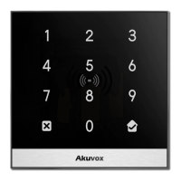
The intercom's primary function is to provide secure access control through multiple methods, including RF card reading and keypad entry (for A02 model). It integrates seamlessly into a network topology, typically utilizing Power over Ethernet (PoE) for both power and data transmission, simplifying installation and reducing cabling requirements. The device is designed for both wall-mounting and flush-mounting installations, offering flexibility to suit different architectural and aesthetic preferences.
Upon receiving the Akuvox A01/A02/A03 intercom, it is essential to verify that all necessary components are present in the shipped box. The universal accessories provided include various screws (M2.5x4 crosshead, ST4x20 crosshead, M4x30 crosshead, M3x4 headless), a rope, a pry bar, plastic wall anchors, a silicone foam seal strip, an Allen wrench, an RJ45 Ethernet patch cable, rubber plugs (S, M, L), an RJ45 coupler Ethernet extension connector, an embedded junction box mounting bracket, and a cable locking plate. The package also includes one unit of the A01, A02, or A03 device itself. These accessories are crucial for the secure and proper installation of the intercom.
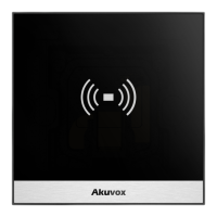
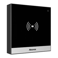
The Akuvox A01, A02, and A03 models share core functionalities but differ in their user interface features. All models incorporate a card reader, allowing users to unlock doors by placing a predefined RF card in the designated area. The A02 model further enhances access control with an integrated keypad, enabling numerical code entry for authentication. All models are equipped with Bluetooth connectivity, which can be leveraged for additional functionalities or configuration options. The robust design and comprehensive set of accessories ensure that the device can be securely installed and maintained in various settings.
The installation process is detailed for both wall-mounting and flush-mounting scenarios, ensuring adaptability to different building structures.
The first step involves bracket installation. Users are advised that an 86 junction box is a standard purchased item and not included in the packing list, so it must be prepared beforehand. To begin, mark the positions of the four holes of the junction box at the hole center, ensuring the junction box is at least 1100 mm in height. Next, drill the four marked holes using a 6mm drill bit, to a depth of 30mm. Insert the plastic wall anchors into these drilled holes. Then, fix the junction box onto the wall using four ST4x20 crosshead screws. Finally, fix the junction box component onto the junction box using two M4x30 crosshead screws. Once these steps are completed, the junction box installation is finished.
For flush mounting, a square hole with dimensions of 86mm (height) x 86mm (width) x 33mm (depth) needs to be cut. A cable should be led from this square hole into the junction box. If the junction box is already embedded in the wall, this step can be skipped. After cutting the hole, fill any gaps between the square hole and the junction box with cement or another non-corrosive construction adhesive. It is important to wait until the cement or adhesive has hardened before proceeding. Similar to wall-mounting, if the junction box is already embedded, this step is also skipped. Once the adhesive is set, fix the junction box component onto the junction box using two M4x30 crosshead screws. This completes the junction box installation for flush mounting.
After the junction box is installed, the back cover installation begins. For ease of installation, it is recommended to lead the provided rope through the rope hole at the back of the device and then fill the groove with the silicone foam strip. The rope is then hung onto the hook hanger on the junction box.
Next, the RJ45 cable (without a sleeve) is inserted, and the terminal slot is pressed down using the pry bar to secure all signal wires in their corresponding slots. It is crucial to ensure that all connection wires are organized under the wire organizer. If an RJ45 extension cable with a sleeve is used, an RJ45 Ethernet patch cable should be inserted first and connected to the RJ45 coupler Ethernet connector before connecting the sleeved RJ45 cable to the connector. This ensures proper sealing against water.
Rubber plugs are then inserted into the corresponding plug openings in the indicated direction. The size of the rubber plug depends on the quantity of signal wires: a small plug for less than 6 wires, a medium plug for 7-10 wires, and a large plug for 11 or more wires.
Finally, all cables are routed through the groove of the cable locking plate. The device is then hung onto the junction box mounting bracket, pushing it down against the corresponding hook hanger. The cable locking plate is inserted and tightened using four M2.5x4 crosshead screws.
The final step in installation is device mounting. Push the device against the hook hanger and tighten it with an M3x4 headless screw using the Allen wrench. This completes the physical installation of the device.
The Akuvox intercom supports various wiring connections for comprehensive access control. These include:
To ensure optimal performance and prevent voltage drop, it is crucial to use the correct wire gauge based on the cable length. For a 12V 1A adapter:
The Akuvox A01/A02/A03 intercom typically operates within a Local Area Network (LAN), often utilizing Power over Ethernet (PoE) switches. This setup allows the intercoms (A01/A03 and A02 models) to receive both power and data through a single Ethernet cable, simplifying wiring. A PC within the same network can then be used to configure and manage the intercoms.
Configuring the Akuvox intercom involves a few straightforward steps:
To unlock a door using an RF card, simply place the predefined RF card in the RF reader area on the device. The intercom will then grant access.
While the manual does not explicitly detail a dedicated "maintenance features" section, several aspects of the device and its installation imply ease of maintenance:
In summary, the Akuvox A01/A02/A03 Smart Intercom is a comprehensive access control solution designed for ease of installation, flexible configuration, and reliable operation, with inherent features that contribute to its maintainability and longevity.
| Interface | Ethernet |
|---|---|
| Case design | - |
| Event capacity | 100000 |
| Number of users | 20000 user(s) |
| Card holders quantity | 20000 |
| Maximum number of doors | 1 door(s) |
| Supported network protocols | IPv4, HTTP, HTTPS, FTP, SNMP, DNS, NTP, RTSP, RTP, TCP, UDP, ICMP, DHCP, ARP |
| Ethernet LAN data rates | 10, 100 Mbit/s |
| DC voltage range | 12 V |
| Power consumption | 600 mA |
| Ethernet LAN (RJ-45) ports | 1 |
| Storage temperature (T-T) | -30 - 70 °C |
| Operating temperature (T-T) | -20 - 55 °C |
| Operating relative humidity (H-H) | 10 - 90 % |
| Depth | 33 mm |
|---|---|
| Width | 86 mm |