3 COMPONENTS AND FEATURES OF THE RADIO
3.1 Front side
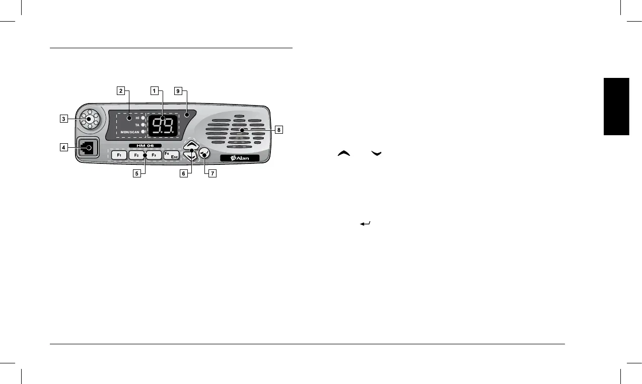
[1] Display (two-digit LED display with seven segments) – Displays the
information described below, depending on the operating mode:
• Instandbymode – Continuously displays the operating channel.
• Inotheroperatingmodes(forexampleduringtheadjustment
of squelch) – Displays different information depending on the
selectedmode(forexamplethecurrentsquelchlevel).
[2] Signaling LEDs – These three LEDs respectively signal (from
top to bottom):
• HI (red) – Indicates that a high power transmission is enabled
on the currently selected channel. For additional information,
seeparagraph6.7.c.
• TA (green) – Indicates that the Talk-Around feature is enabled.
For additional information, see paragraph 9.3.
• MON/SCAN – If this LED is permanently on, it indicates that the
Monitoring feature has been enabled. For additional information, see
paragraph6.6. IftheLEDisashing,itindicatesthat thechannel
scan is in progress. For additional information, see paragraph 9.1.
[3] On/Off Volume Knob
[4] Microphone jack
[5] Programmable function keys: F1, F2, F3 and F4/ESC
2 Key F4/ESC can also be used to quit the squelch adjustment
feature without saving the new setting. For additional informa
-
tion, see paragraph 6.5.
[6] (Up) / (Down) keys – These keys can be used for several tasks:
• Instandbymode – To select the operating channel.
• Duringtheadjustmentofsquelch – To adjust the trigger level (see
paragraph 6.5).
•
While a scan is in progress–Tomovetothenextchanneland
resume the channel scan (see paragraph 9.1).
[7] Key (Enter):
• Instandbymode – Enables the feature linked to the key during
theprogrammingphase(seeparagraph7.1).
• Duringtheadjustmentofsquelch–Conrmsthecurrentlydis
-
played level (see paragraph 6.5).
[8] Speaker –
[9] Status LED:
• Red – Transmission
• Green – Reception of signals (busy channel)
• Orange – Receipt of signals with a correct CTCSS/DCS tone/code