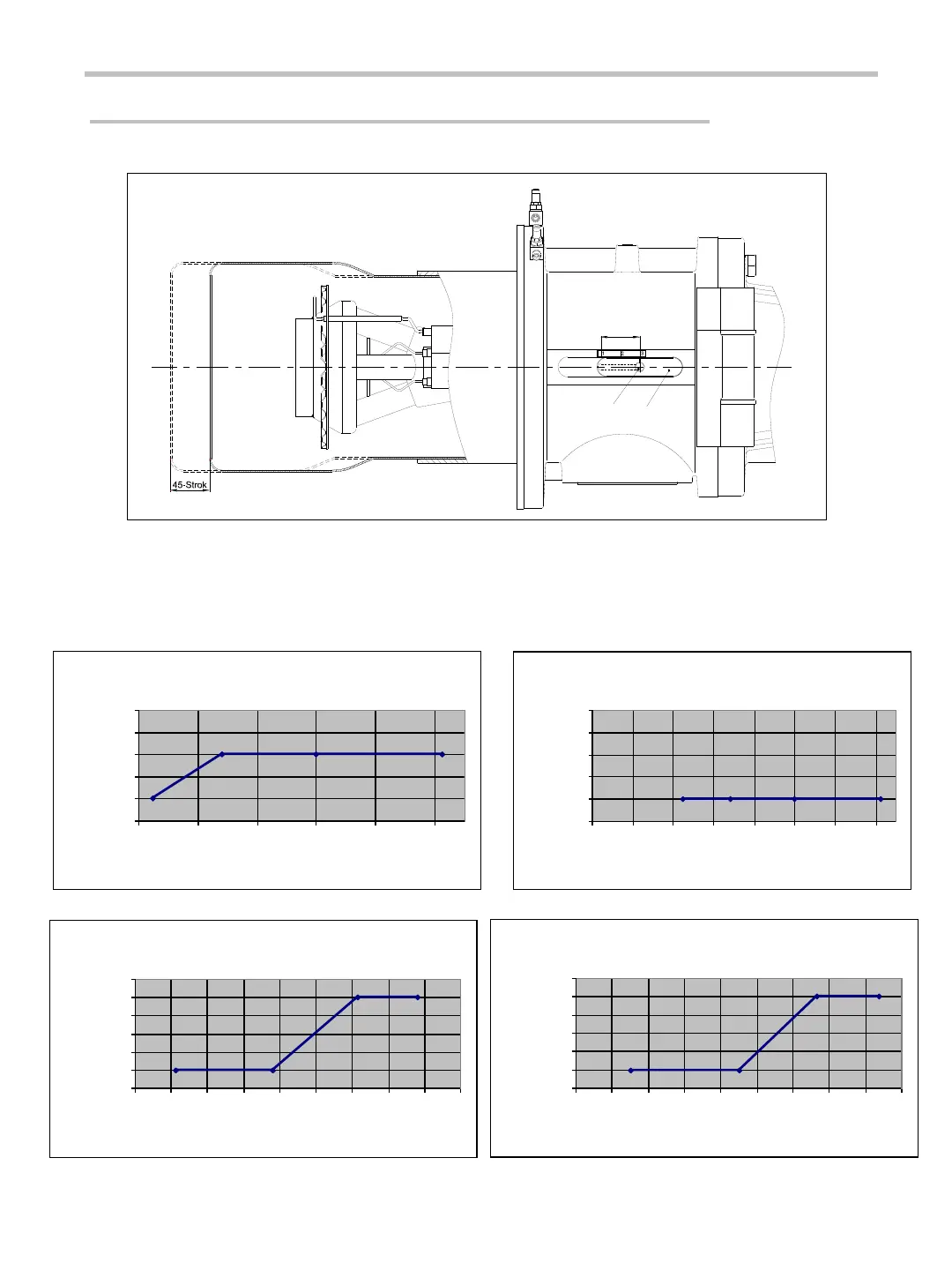
The combustion head and turbulator must be placed correctly in order to achieve a proper combustion
efficiency.
The turbulator can be placed to min, medium and max (1, 2, 3) values by unscrewing the nuts. The
position of the combustion head relative to the turbulator is adjusted and nuts are tightened when
positioning is ended. The air flow cross-section area is varied with this method. The correct position
can be found by utilizing the below graphs.
18
COMBUSTION HEAD – TURBULATOR ADJUSTMENT
Stroke length
Nut
Head Adjustment Cover
0,5
1
1,5
2
2,5
3
800 1000 1200 1400 1600 1800
0,5
1
1,5
2
2,5
3
400 600 800 1000 1200 1400 1600 1800
0,5
1
1,5
2
2,5
3
3,5
400 500 600 700 800 900 1000 1100 1200 1300
0,5
1
1,5
2
2,5
3
3,5
400 500 600 700 800 900 1000 1100 1200 1300


 To Next Page