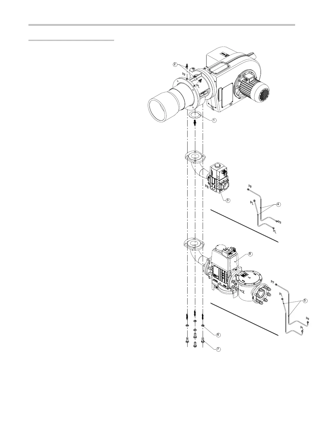
ALG 200/M GAS LINE (MBC Series with filter)
Gas line connection to the burner must be done via
placing the gasket (1) between the gas line (8) and
the flange using the washers (6) and bolts (7) which
are supplied along with the burner as shown in the
relevant figure. After the gas line is assembled, the
caps on the connection body must be removed.
Measurement control nipples (2) are connected to
appropriate places at tips as shown in figure. The
measurement piping set (indicated as #5) must be
connected to the measurement control nipples and
to the tips on the gas line where indicated by letters.
ALG 200/M ,ALG 120/M GAS LINE (MBC Series)
Gas line connection to the burner must be done via
placing the gasket (1) between the gas line (3) and
the flange using the washers (6) and bolts (7)
which are supplied along with the burner as shown
in the relevant figure. After the gas line is
assembled, the caps on the connection body must
be removed. Measurement control nipples (2) are
connected to appropriate places at tips as shown
in figure. The measurement piping set (indicated
as #4) must be connected to the measurement
control nipples and to the tips on the gas line
where indicated by letters.
23
GAS LINE ASSEMBLY
Gas line assembly must be done by an
authorized service according to the the
regulations stated in this manual.
The weight of the gas line should not be
balanced (carried) by the burner prior to
tightening of the bolts.
The rules for gas line assembly of
attention are stated below for each type:


 To Next Page