Do you have a question about the Alcatel Vacuum Technology Adixen ATH 1600 MT and is the answer not in the manual?
| Brand | Alcatel Vacuum Technology |
|---|---|
| Model | Adixen ATH 1600 MT |
| Category | Water Pump |
| Language | English |
Lists applications like semiconductor processes and research.
Highlights features such as high throughput, quiet operation, reliability.
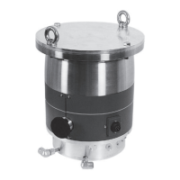
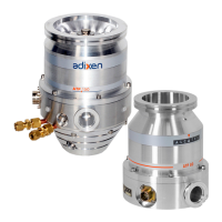
Overview of the pump and its controller.
Explains how the turbomolecular pump operates.
General description of the pump's features and components.
Details about the ACT 1300 M controller.
Lists available accessories for the pump.
Provides detailed technical specifications of the pumps.
Document certifying compliance with SEMI S2-93 A standards.
Essential safety guidelines before operating the pump.
Procedures for unpacking and storing the pump.
Guidance on connecting the pump to a system.
Details on connecting the inlet and exhaust ports.
Instructions for connecting the optional air inlet valve.
How to connect the nitrogen purge device.
Information on connecting the water cooling system.
Details on connecting the heating band.
How to make electrical connections for the pump and controller.
Wiring for the dry contacts connector.
Wiring for the inputs/outputs connector.
Wiring for the remote connector.
How to wire RS 232 or RS 485 serial links.
Explains commands for RS232 and RS485 communication.
Safety guidelines for operating the pump.
Steps to start up the controller.
How to configure the controller for specific applications.
Operating the pump via the controller's front panel.
How to operate the pump in local or remote modes.
How the external safety contact functions.
How the inhibit mode operates.
Safety guidelines for maintenance procedures.
Steps to diagnose and resolve pump issues.
Procedures for safely shipping contaminated pumps.
Information on using spare parts.
List of common maintenance parts.
Graphs showing pump performance at different pressures.
Questionnaire for returning equipment for service.
Document confirming compliance with standards.
Basic description of the pump technology.
Details on the magnetic bearing system and control.
Explanation of the automatic balancing system for reduced noise.
Indicates that the pump requires no routine maintenance.
Function of the inert gas purge system.
Description of the battery-free operation during power failure.
Functionality of the integral heater band for temperature control.
Detailed information on the ACT 1300 M controller.
Features of the new ACT controller family.
Description of the controller's user interface.
Capabilities for pump monitoring and power supply compatibility.
Power supply specifications for the heater.
Interface options for control and status signals.
Explanation of the hybrid technology used in the pumps.
Function of the turbomolecular section.
Function of the molecular drag section.
Description of the rotor and its magnetic suspension.
Illustration of controlled translations.
Illustration of controlled rocking.
Explanation of the automatic balancing system.
Description of the back-up bearings and their use.
Information about the pump's low maintenance design.
How the pump operates during power failure.
How the hybrid-turbo pump integrates into an installation.
Overview of the standard pump versions with gas purge.
Benefits of the gas purge feature.
Overview of the MT versions with built-in heater band.
Function of the built-in heater band.
How to vary the pump's rotational speed.
Physical dimensions and weight of the controller.
Description of the controller's front panel interface.
Keys for parameter selection and configuration.
Keys for manual pump control.
Components on the rear panel of the controller.
Connector for the power supply.
Connector for the pump.
Terminal strip for relay connections.
Connections for analog output and RS485 serial link.
Connector for RS232 serial link.
Connector for inputs and outputs.
Grounding connection instructions.
Description and part numbers for screen filters.
Device to reduce purge gas flow rate.
Valve to maintain vacuum during reset.
Valve to slow down pump safely and its cable.
Interconnecting cables for pump and controller.
Cable to connect controller to power supply.
Interconnecting cable for heating band and controller.
Performance data for ATH 1300 M/MT and ATH 1600 M/MT pumps.
Technical specifications of the ACT 1300 M controller.
Dimensional drawings of the ACT 1300 M controller.
Dimensional data for ATH 1300 M/MT pumps with DN 200 ISO-F.
Dimensional data for ATH 1600 M/MT pumps with DN 200 ISO-F.
Dimensions of the water valve.
Dimensions of the air inlet valve.
Crucial safety precautions before operation and installation.
Requirements for electrical installation grounding.
Alcatel's disclaimer regarding product modifications.
Information on missing EMO and LO/TO devices.
Warning about electrical shock risk from rotating parts.
Guidelines for EMC performance and magnetic field exposure.
Warnings regarding capacitor discharge and handling heavy objects.
Precautions against tilting during handling and operation.
Warning about using the pump as a compressor and manual study.
Dangers of accessing the rotor and importance of interlocks.
User responsibility for maintaining leaktightness with dangerous gases.
Safety measures for process pumps regarding purge flow.
Safety measures for handling flammable/toxic gases with exhaust monitoring.
Warning about hot surfaces and necessary precautions.
How the safety interlock and overload protection work.
Explains various warning labels on the pump housing.
Hazards related to pumped process gases and maintenance by trained personnel.
Recommendation to secure the turbopump installation for safety.
Instructions for careful unpacking and keeping packaging.
Precautions for tilting risk during handling and operation.
Illustration of pump, controller, and cables.
Details on what is included in the packaging.
Weight information for handling the controller and pump.
Recommendations for storing the pump and its connections.
Recommended storage temperature for the controller.
Importance of securing the pump installation for user safety.
General specifications for installing the pump.
Instructions for connecting the pump according to items 1, 2, 3.
Definitions of crash scenario loads.
Description of axial loads on the system.
Description of bending moments on the system.
Description of torque transmitted to the system.
Illustration of loads transmitted to the system.
Graphs showing transmitted forces on test bench for ATH 1300 M and 1600 M.
Requirements for inlet flange installation and bolt tightening.
Recommendation to use ISO-F or CF-F flanges over ISO-K.
Optional equipment installation conditions for frame rigidity.
Illustration showing pump can operate in any position.
Precautions for vacuum connections and handling corrosive gases.
Instructions for installing the screen filter accessory.
Steps for mounting the insertable inlet flange.
Recommendation and function of the secondary isolation valve.
Instructions for mounting the removable inlet flange.
Importance of the primary isolation valve at the exhaust.
Purpose of the air inlet valve for resetting volume and rotor speed.
Connecting the air inlet valve without a purge device.
Connecting the air inlet valve with a purge device.
How to electrically connect the air inlet valve.
Instructions for protective earthing of the air inlet valve cable.
Required characteristics for the dry nitrogen supply.
Connecting the nitrogen purge without an air inlet valve.
Connecting the nitrogen purge with an air inlet valve.
How to stop purge during pump operation.
Continuous operation of the nitrogen purge.
How to adjust the nitrogen purge flow rate.
Recommended water cooling characteristics.
Water cooling connection for standard models.
Water cooling connection for MT models.
Electrical connection for the water valve.
Instructions for protective earthing of the water valve cable.
Information for thermostated MT models with heating band.
How to connect the thermostatic cable for heating.
How heating band temperature is regulated by the controller.
Safety precautions for electrical connections.
Information on internal connections and main power supply.
Symbol on rear panel and circuit breaker requirements.
Information on EMO device and external stop system connection.
Requirements for controller installation environment.
Overview of various connections for the controller.
Instructions for controller frame grounding.
Step-by-step guide to connect pump and controller.
Instructions for connecting to the controller's connector.
Steps for plugging the connector and tightening screws.
Importance of checking surface contact for proper installation.
How to make the main power connection at the rear of the controller.
Wiring diagram for typical connection and temperature regulation.
Purpose of dry contact outputs for signaling pump status.
Specifications for dry contact outputs.
Specifications for controller outputs.
Table showing functional status of contacts.
How to control the pump via voltage inputs.
Controlling the pump using dry contacts in input mode.
Table detailing command modes for input control.
Description of dry contact outputs and their functions.
Location and purpose of the "Rem." connector.
How the analog output signal is transmitted.
Default settings for RS 232 serial link.
Wiring diagram for the RS232 connector.
Example of an RS232 serial link setup.
Wiring details for the "Rem." connector.
How to set up multiple RS485 serial links.
Syntax conventions for all commands.
Possible status values for commands.
Common error messages and their meanings.
Command to specify device address for networking.
Command to list detected faults.
Commands to list analog and logical inputs/outputs.
Command to identify the device and its software version.
Command to retrieve the state of SET parameters.
Command to set speed to nominal value.
Commands to select user choices for analog output and temperature units.
Command to define the standby speed set point.
Command to switch speed set point to standby value.
Commands to list all data, analog inputs/outputs, logical inputs/outputs.
Command to return the state of parameters defined by OPT.
Command to define the parameter separator character.
Commands to define internal operating parameters.
Command to return the current speed.
Command to return the status of internal dynamic parameters.
Continuation of STA command details.
Command to list data titles.
Command to define the operating state of the pump.
Checks before using the controller and operational warnings.
Warnings about thermal risks and proper pump handling.
Purpose of the air inlet valve for pump safety.
Recommended components for pump installation.
Reference to maintenance chapter D10.
Process of controller self-test and initialization.
What is shown during display initialization and light tests.
Explanation of parameter setting keys and display messages.
How to configure parameters using controller menus.
Setting the access code and configuring remote mode.
How to configure the 0-10V analog output.
Settings for standby speed and auto-starting.
Configuration options for buzzer, temperature unit, and heating.
Settings for relay speed, serial link, and start delay.
Configuration of venting times and bearing alert thresholds.
Settings for pump running time and access code modification.
Configuration options for serial link settings.
Setting the controller address for multiple links.
Explanation of indicator lights for pump status.
How to start the pump using the controller.
How to select the reduced speed mode.
How to stop the pump using the controller.
How to view pump and controller status information.
How to display the last 10 faults.
How to display the last 10 alerts.
How to view bearing life time and alert threshold.
Diagram of the pumping cycle.
Instructions for local mode operation and connector requirements.
Steps to switch on and start the pump.
How to initiate pumping using the START button.
Instructions for wiring and operating valve V2.
How to select standby mode.
How to stop the pump operation.
Instructions for opening valve V3.
Instructions for closing valve V3.
Instructions for closing valve V2.
Advice on limiting immediate restarts.
How the pump behaves during a power cut.
Controller display and behavior during short power cuts.
Instructions for remote mode operation and connector wiring.
How the external safety contact operation mode works and is indicated.
Steps to restart the pump when external safety is active.
Behavior of the pump when inhibit mode is disabled.
Behavior of the pump when inhibit mode is valid.
General safety steps before performing maintenance.
Precautions for handling corrosive/toxic gases and using blank flanges.
Importance of locking/tagging out chemical supplies.
Checking pump conditions before maintenance.
User responsibility for maintaining tightness with dangerous gases.
Advice on N2 flow and safety during exhaust maintenance.
Maintenance requirements for back-up bearings and bearing counter.
Setting bearing alert thresholds and interpreting messages.
Troubleshooting issues related to default types and screen status.
Diagnosing and resolving screen blockage issues.
Troubleshooting microprocessor and power supply issues.
Identifying defect types and interpreting signal lights.
Troubleshooting seized pumps and power overheat issues.
Diagnosing motor and control overheat problems.
Troubleshooting hall sensor defaults and overcurrent conditions.
Diagnosing external safety contact and magnetic suspension issues.
Troubleshooting power supply failures and overcurrents.
Troubleshooting rotor position and bearing life time alerts.
Diagnosing controller and pump temperature problems.
Troubleshooting pump failures and sensor errors.
Troubleshooting memory issues and EEPROM checksum errors.
Diagnosing pump-controller incompatibility and wiring faults.
Steps for troubleshooting multiple apparent defects.
Troubleshooting when no event occurs after power on.
Diagnosing standby mode start-up and motor load problems.
Troubleshooting pump vibration issues.
Troubleshooting steps for pump not reaching expected speed.
Diagnosing issues with a closed exhaust isolation valve.
Troubleshooting defective rough pumping.
Diagnosing issues with the air inlet valve staying open.
Troubleshooting why the thermostatic temperature is not reached.
Requirements for filling safety questionnaire and return procedures.
Description of inlet port closing kits.
Accessories for exhaust and purge ports.
Accessories needed for the purge port.
Steps for decontamination before shipping.
Procedure for pressurizing the pump with dry nitrogen.
Guidelines on replacing parts and using non-genuine parts.
Part numbers for copper seals for CF-F flanges.
Part number for ASA 6" O-ring.
Part numbers for controller fuses.
Part numbers for air inlet valve accessories.
Part numbers for water valve components.
Graphs showing pumping speed vs. inlet pressure for N2 and H2.
Graphs showing flow rate vs. inlet pressure for N2.
Procedure for returning equipment for maintenance.
Information on potential contamination risks.
How to indicate chemical contamination in the system.
Fields for company, person, equipment, and serial number.
Details regarding desired service interventions.
Information on copper process and safety aspects.
Confirmation of contact with substances and necessary precautions.
Confirmation of ISO 9001 certification.
List of European Directives with which products comply.
List of norms and specifications the products comply with.