ELECTRICAL CHARACTERISTICS
16
6.4. DC Electrical Characteristics for 5 volts operation
( Under Recommended Operating Conditions and V
CC
=4.5v ~ 5.5v , Tj= -40
O
C to + 85
O
C )
SYMBOL PARAMETER CONDITIONS MIN TYP MAX UNITS
V
IL
Input Low Voltage TTL 0.8 V
V
IL
Input Low Voltage CMOS 0.3*V
CC
V
V
IL
Schmitt input Low Voltage TTL 1.10 V
V
IL
Schmitt input Low V oltage CMOS 1.84 V
V
IH
Input High Voltage TTL 2.2 V
V
IH
Input Hight Voltage CMOS 0.7*V
CC
V
V
IH
Schmitt input High Voltage TTL 1.87 V
V
IH
Schmitt input High Voltage CMOS 3.22 V
V
OL
Output low voltage I
OL
=2, 4, 8, 12, 16, 24 mA 0.4 V
V
OH
Output high voltage I
OH
=2, 4, 8, 12, 16, 24 mA 3.5 V
R
I
Input Pull-up/down resistance Vil=0
V
or Vih=V
CC
50
KΩ
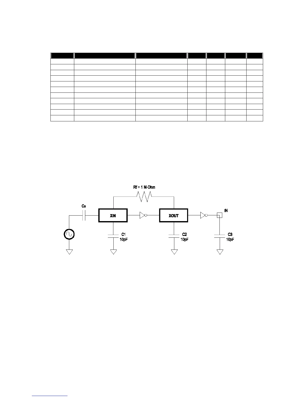
6.5. Crystal Oscillator Circuit Setup for Characterization
The following setup was used to measure the open loop voltage gain for crystal oscillator
circuits. The feedback resistor serves to bias the circuit at its quiescent operating point and
the AC coupling capacitor, Cs, is much larger than C1 and C2.