ELECTRICAL CHARACTERISTICS
22
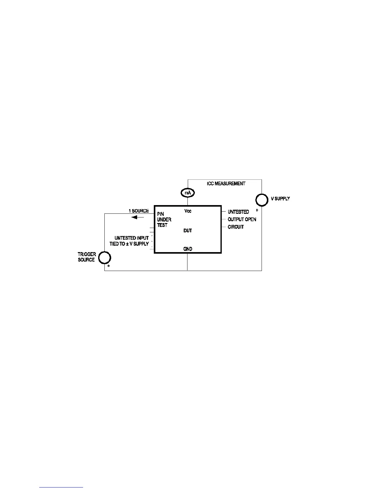
6.8. Latch-Up Test Results
Test Description: Latch-Up testing was performed at room ambient using an IMCS-4600
system which applies a stepped voltage to one pin per device with all other pins open except
Vdd and Vss which were biased to 5Volts and ground respectively.
Testing was started at 5.0V (Positive) or 0V (Negative), and the DUT was biased for 0.5
seconds.
If neither the PUT current supply nor the device current supply reached the predefined limit
(DUT=00mA, Icc=100mA), then the voltage was increased by 0.1Volts and the pin was tested
again.
This procedure was recommended by the JEDEC JC-40.2 CMOS Logic standardization
committee.
Notes:
1. DUT: The device under test.
2. PUT: The pin under test.
Test Circuit: Positive Input/Output Overvoltage/Overcurrent