SYSTEM ARCHITECTURE AND REFERENCE DESIGN
18
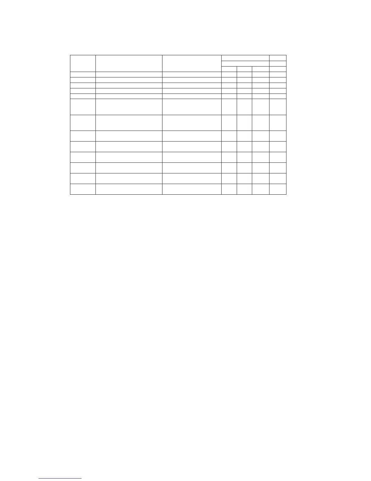
DC ELECTRICAL CHARACTERISTICS
Over recommended operating conditions. Voltages are referenced to GND (Ground=0V)
.
LIMITS
-40
˚
C to +85
˚
C UNIT
SYMBOL PARAMETER TEST CONDITIONS
MIN TYP MAX
VHYS Hysteresis on inputs Vcc=3.0V to 3.6V (Note 3) 0.3 0.4 0.5 V
VIH HIGH level input Vcc=3.0V to 3.6V (Note 3) 1.5 2.0 V
VIL LOW level input Vcc=3.0V to 3.6V (Note 3) 0.8 1.1 V
RoH Output impedance (HIGH state) Note 2 28 34 43 ohm
RoL Output impedance (LOW state) Note 2 28 35 43 ohm
VOH HIGH level output
(Note 3)
Vcc=3.0V Io=6mA
Vcc=3.0V Io=4mA
Vcc=3.0V Io=100µA
2.2
2.4
2.8
2.7 V
VOL LOW level output
(Note 3)
Vcc=3.0V Io=6mA
Vcc=3.0V Io=4mA
Vcc=3.0V Io=100µA
0.3 0.7
0.4
0.2
V
IQ Quiescent supply current Vcc=3.6V VI=Vcc or GND
Io=0
330 600 µA
Isup Supply current in suspend Vcc=3.6V VI=Vcc or GND
Io=0
70 µA
IFS Active supply current (Full
Speed)
Vcc=3.3V 9 14 mA
ILS Active supply current (Low
Speed)
Vcc=3.3V 2 mA
ILeak Input leakage current Vcc=3.6V VI=5.5V or GND,
not for I/O Pins
+/-
0.1
+/-0.5 µA
IOFF 3-state output OFF-state current Vi=Vih or ViL; Vo=Vcc or
GND
+/-10 µA
NOTES:
1. All typical values are at Vcc=3.3V and Tamb=25
˚
C.
2. This value includes an external resistor of 24 ohm +/-1%. See "Load D+ and D-" diagram for
testing details.
3. All signals except D+ and D-.