AR2000 SLIDING GATE OPERATOR
10
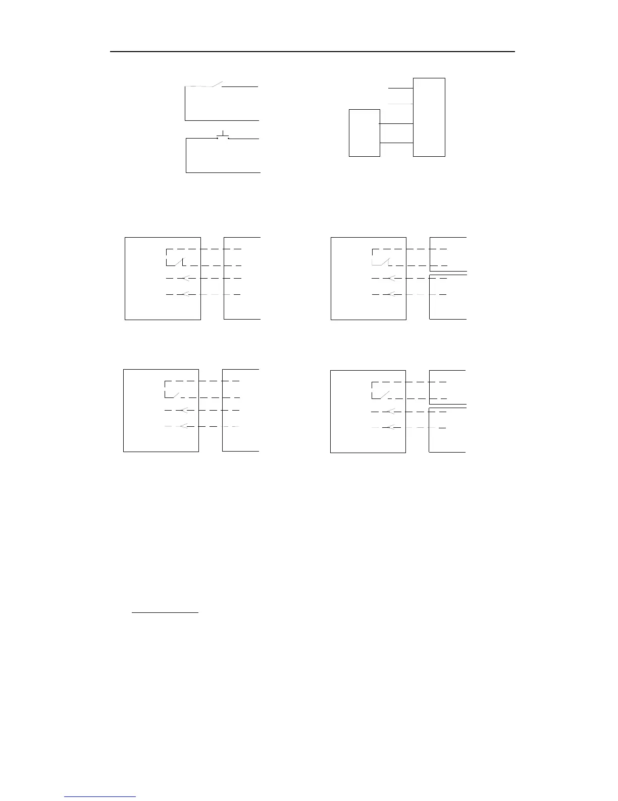
Control board
terminal X7
Button switch
keypad
Not used
G
T
K
Com
Signal
NO
com
K
Open
G
com
NO
GND
Schematic diagram Wiring diagram
15. Output power supply: +12V (DC +12V), COM (CO),DET (Loop detector), I.R. (Infrared N.C)
DET
COM
Out
COM
AC24V AC24V
Terminal
X5,No.11
Loop detector
Control board
COM
GND
+12V
Out
COM
DET
COM
+12V
Loop detector
Control board
Loop detector with DC input
Infrared with DC input
Control board
Infrared
Control boardInfrared
Terminal
X5,No.11
AC24VAC24V
COM
Out
COM
I.R
+12V
COM
I.R
COM
Out
+12V
GND
COM
Terminal
X8, No.15
Terminal
X8, No.15
Terminal
X8, No.15
Terminal
X8, No.15
Loop detector with AC input
Infrared with AC input
Schematic diagram
16. Beeper: DC12V
17. Learn button: AN
18. Dip-switch
19. Antenna: ANT
7. Control
z Remote control:
The remote control works in a single channel mode. It has four buttons.
See Fig.10 Remote control. The function of button 1, button 2 and button3 are the same.
With each press of the remote control button, which has been programmed, the gate will
close, stop, open or stop cycle. Button 4 is available to set pedestrian mode.
You can program/learn button 1, button 2, button 3 individually. You also can program/learn
two buttons or three buttons together, but you need repeat the program/learn process if you
want to use more than one button.