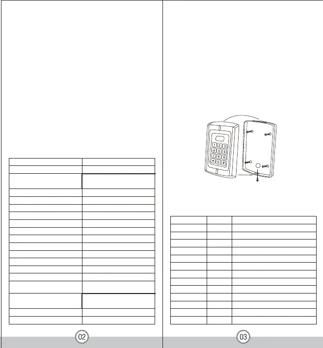
5. Inst allat ion
> PIN length: 4- 8 digits; Card type: 125KHz EM card
> Can be used as a stand alone keypad
> Pulse mode, Toggle mode
> B lock enrollment, can enroll 1100 consecutive cards
within 1 minute
> B acklight keypad
> Adjustable door relay output time, alarm time, door open
time
> B uilt in light dependent resistor (LDR) for anti tamper
> B uilt in buzzer
> Two- relay output for door opening, door status detecting,
open door by button
> Red, yellow and green LED display the working status
> Support door bell connection(Zo
ne 2)
> 1 2-24V DC/12- 18V AC power input
> Two- year warranty
4. Specifications
Operating Humidity
Environment
Adjustable Door Relay time
Adjustable Alarm Time
Wiring Connections
5%- 9 5% RH
Conforms to IP68
1- 99 seconds
0- 3 m inutes
Electric Lock, Exit Button,
DOTL, Ext er nal Alar m
Operating Temperature -40
℃- 60℃
Operating Voltage
User Capacity
Keypad
Card Type
Card Reading Distance
PIN length
Active Current
Idle Current
Lock Output Load
Alarm Output Load
12-24V DC/12-18V AC
1200
EM card
3- 6 cm
4- 8 digits
60mA
25± 5 mA
Max 20A
Max 2A
Dimensions
Net Weight
Gross Weight
650 g
800 g
L128x W82 x H28 mm (
LM178
)
> Remove the back cover from the keypad using the
supplied security screwdriver
> Drill four holes on the wall for the screws and 1 hole for
the cable
> Fix the back cover firmly on the wall with 4 flat head
screws
> Thread the cable through the cable hole
> Use the supplied rubber bungs to waterproof the screw
holes
> Attach the keypad to the back cover
Negative Pole
Alarm Negative
Request to Exit Button of Zone 1
Door Status Detecting
12-24V DC/12-18V AC Power Input
12-24V DC/12-18V AC Power Input
Request to Exit Button of Zone 2
Grey & Black
Grey
Yellow
Brown
Red
Black
Blue& Black
White&Black
White
Yellow & Black
Green& Black
Blue
Green
GND
Alarm -
OPEN1
D_IN
AC&DC
AC&DC
NO2
COM2
COM1
OPEN2
NC2
NO1
NC1
6. Wiring
Colour Function
Description
12 keys, 3 x 4 digits ( )
LM178
LM178
 Loading...