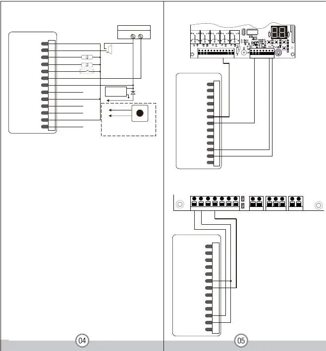
Connection Diagram
12-24V DC/12-18V AC/5A
Power
-
+
+
-
Alar m
Door Stat us Detec ting
Door Bell
Request to Exit Button of Zone 2
Request to Exit Button of Zone 1
Electric Lock
Diode
NO 2 White
COM 2( Green/White)
Door Bell i nstallation & usage:
Connect door bell w ith wir es:NO2 COM2 .
Press ‘ # ’ ,the W1-A/ W3- A reader will
send outa signal to the door b ell.
Remarks:
The Zone 2, it can be used to operate the door bell when no
need to operate a second door. The wiring is connecting the
door bell to NO2 and COM2. Press #, the reader will send
out a switching signal to the door bell, as long as you press
the “ #” , the door bell will continuous operate, it will stop
until you release the “ #”
Connect the negative pole of the lock to NC is for Fail safe
lock.
Connect the negative pole o
f the lock to NO is for Fail secure
lock.
LM178
Yellow OPEN1
Brown D_IN
Red
Black
AC&DC
AC&DC
Blue & Black
NO2
Green & Black
2MOC & kcalB etihW
NC2
Blue NO1
2NEPO& kcalBwolleY
Grey&Black GND
ALARM
NC1
COM1
Green
White
Grey
Yellow OPEN1
Brow n D_IN
Red
Black
AC&DC
AC&DC
Blue & Black
NO2
Green & Black
2MOC & kcalB etihW
NC2
Blue NO1
2NEPO& kcalBwolleY
Grey&Black GND
ALARM
NC1
COM1
Green
White
Grey
1 2 3 4 5 6 7 8 9
10 11 12
+ MOTOR1 - ULT1 COM DLT1 + MOTOR2 - ULT2 COM DLT2 + LAMP -
13 14 15 16 17 18 19
20
+ BAT - PHOTOCELL O/S/C
INC FUNC DEC
LEARN
AS & GateGuard Series
2
1
L N
PWRIN
43
V
U
5
W
76
LAMP
98
COM
DWN
10
UP
12
11
COM
PHO
13
O/S/C
OPLD
CLLD
GND
14
AC1500, AR1550, AC2400, AR2450, AC5700,AR5750
Yellow OPEN1
Brown D_IN
Red
Black
AC&DC
AC&DC
Blue & Black
NO2
Green & Black
2MOC & kcalB etihW
NC2
Blue NO1
2NEPO& kcalBwolleY
Grey&Black GND
ALARM
NC1
COM1
Green
White
Grey
 Loading...