LTBT-TM-MSET2 9
Operational Overview
Operational
Overview
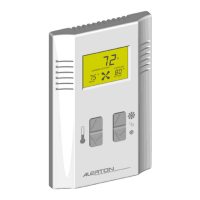
The Microset II operates in one of nine modes. In each mode,
the Microset II displays data and has operational features
unique to that mode. Operating modes are listed in Table 3 on
p. 12 and Table 4 on p. 13.
Review the different Microset II modes and determine which
one is best for your application. Then use DDC in the VLC to
set BVs 64, 65, 80, and 81 according to Table 4 on p. 13.
All Microset II operating logic executes in VLC DDC.
BACtalk data displays can directly reference data points in the
VLC reserved for Microset II operation. This offers the system
operator flexibility and ease of use—with a mouse click, the
system operator can control Microset II operations.
Hotel vs. Office Modes
BV-81 controls hotel and office mode (BV-81 ON = hotel). The
primary difference between hotel and office mode is the
function of the after-hours timer as compared to the function of
the housekeeping timer. See “After-hours Override Operation”
and “Housekeeping Override Operation” herein. Other
operational details vary as well. See “Operating Mode
Specifics” on p. 12.
Fan-control vs. No-
fan-control Modes
BV-80 determines fan control mode (BV-80 ON = fan- control
mode).
In fan-control modes, the occupant can select fan speed at the
Microset II. Fan-control modes are typically used in fan-coil,
air conditioning, or unit ventilator applications.
In no-fan-control modes, the occupant is unable to select fan
speed. However, if desired, VLC DDC can cause fan
symbology to display at the Microset II. No-fan-control modes
are typically used in VAV or heat pump applications.
Cooling and Heating
Setpoint Calculation
The Microset II calculates current heating and cooling
setpoints (AV-99 and AV-100) using different logic in occupied
and unoccupied modes (as read from BV-67). Using the current
setpoints (AV-99 and AV-100) in your control DDC is most
efficient because the VLC automatically calculates these
setpoints according to the operating status of the Microset II.
Occupied Setpoint Logic
(BV-67 ON)
Current cooling setpoint (AV-99) = Occupant-selected
space temperature setpoint
1
(AV-90) + Cooling offset (AV-
93) + Demand offset (AV-106)
Current heating setpoint (AV-100) = Occupant-selected
space temperature setpoint
1
(AV-90) – Heating offset (AV-
94) – Demand offset (AV-106)
Unoccupied Setpoint Logic
(BV-67 OFF)
Current cooling setpoint (AV-99) = Unoccupied cooling
setpoint (AV-95)
Current heating setpoint (AV-100) = Unoccupied heating
setpoint (AV-96)
1. The system’s setpoint high limit (AV-91) and setpoint low limit (AV-92)
limit this value.


 To Next Page