J
johnsonjamesAug 3, 2025
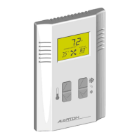
What to do if there's no air flow at the ALERTON MICROSET 4 Accessories sensor?
- MmhurstAug 3, 2025
If there is no air flow at the ALERTON Accessories sensor, it may be due to blockages on the wall around the sensor. Remove any obstructions or relocate the Microset 4 to a clear location. Also, engineering should review mechanical design drawings for sensor and diffuser placements.