© Honeywell LT-MS4IOG Rev. 04 | Revised October 2015
17
INSTALLATION & OPERATIONS GUIDE | MICROSET 4
Typically, precision resistors in the range 80-130 Ohms (+1%) yield acceptable results. Ideally, the
value of the terminating resistors should match the rated characteristic impedance of the installed
cable. For example, if the installed cable has a listed characteristic impedance of 100 Ohm, install 100
Ohm matched precision resistors.
CAUTION Do not mismatch terminating resistors. Ensure that both resistors on a segment have the
same value.
Wiring the wall sensor
CAUTION P
ower must not be connected while wiring. Wiring a unit that is powered may result in electrical shock and/or
equipment damage.
1. Connect wires to the terminal blocks. The terminals are as follows:
2. Secure backplate to mounting surface with screws (provided).
3. Push excess wire back into the hole and plug the hole with non-flammable insulation to
prevent drafts from affecting the wall sensor. Check for loose or frayed wire that may cause
a short.
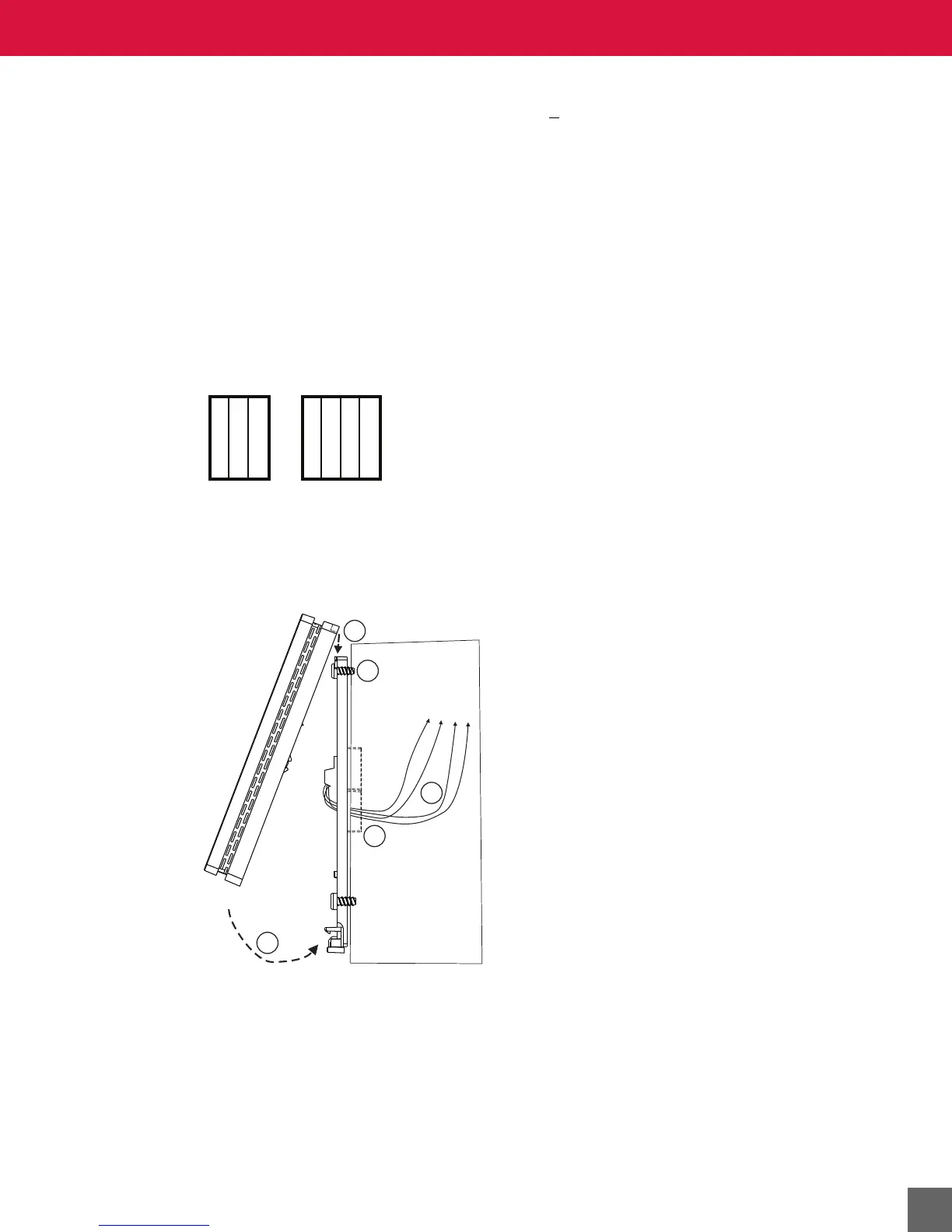
Figure 11 Microset 4 mounting connections.
Mounting the wall sensor on the wallplate
4. Insert Microset 4 tabs into backplate slots. See Figure 11.
5. Push bottom of Microset 4 until it clicks into position. See Figure 11.
6. (Optional) Install security setscrew.
Non-MS/TP MS/TP
24 VAC/DC+
24 VAC/DC+
COM
IN-0/MSET
GND
+MS/TP
-MS/TP