INSTALLATION & OPERATIONS GUIDE | MICROSET 4
© Honeywell LT-MS4IOG Rev. 04 | Revised October 2015
14
Wiring
CAUTION Half-wave devices and full-wave devices must not use the same AC transformer. You must
maintain wiring polarity. Failure to do so can result in equipment damage.
Wire specifications
Maintain polarity of the wire run throughout the LAN.
NOTE Do not run Microset 4 wire in the same conduit or alongside building power cables. This can
cause interference. If power cables must be crossed, cross at 90°.
Power supply guidelines and requirements
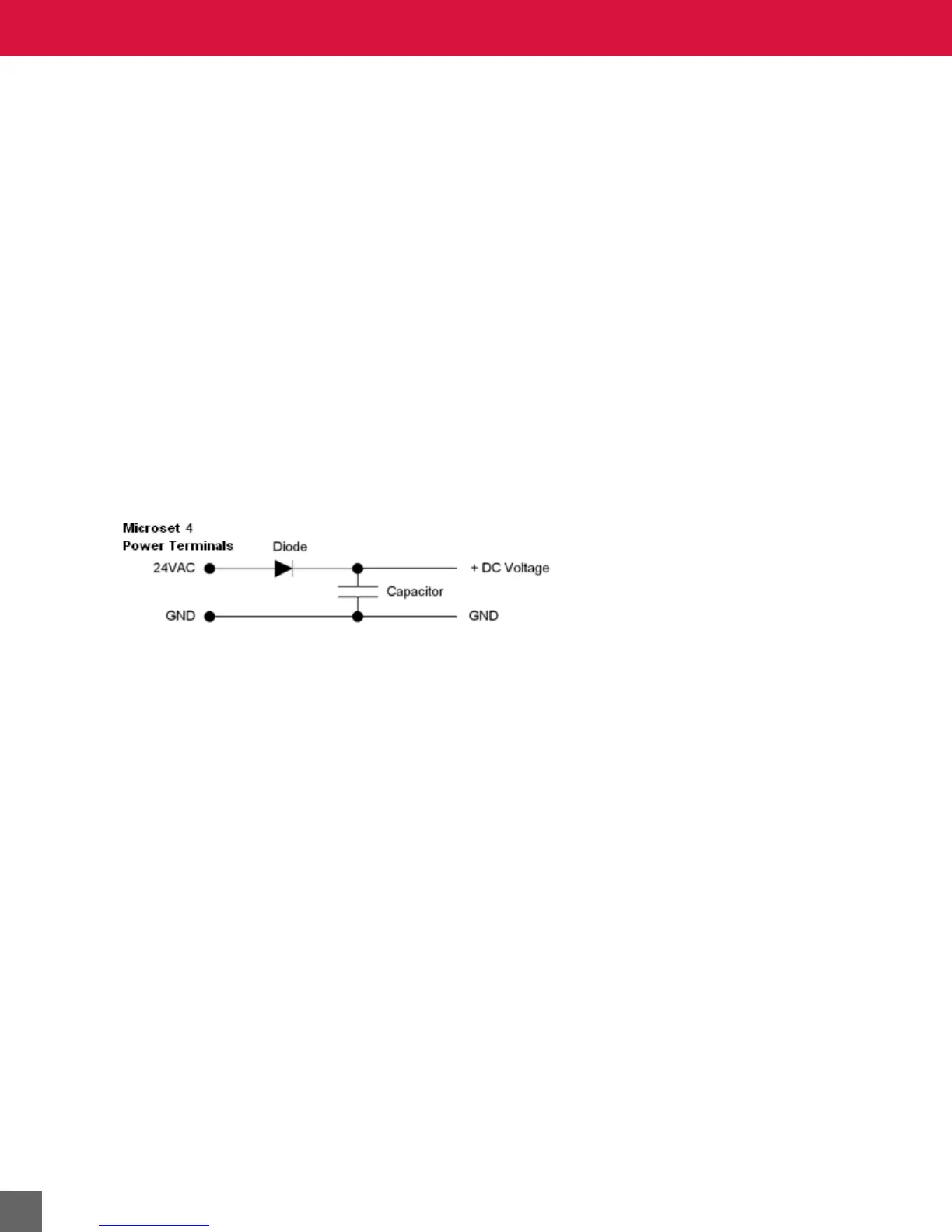
The wall sensor uses 24 VAC power from a UL Listed Class 2, 24 VAC transformer (not provided). The
wall sensor uses a half-wave rectifier to convert the AC power supply to onboard power. Multiple half-
wave devices may be powered from one, grounded transformer.
CAUTION If a Microset 4 will share its power supply with another device, make sure that the other
device utilizes a half-wave rectifier and that polarity of wiring is maintained. Failure to do so
can result in equipment damage.
Figure 8 Internal Microset 4 power wiring schematic, half-wave rectifier.
Microset 4 power ratings
The Microset 4 minimum current draw is 24 VAC @200mA leading to 3VA.
Power supply grounding and wiring
When connecting power to the Microset 4, ensure that one leg of the VAC secondary circuit connects to
a known earth ground.
Supplying a high-quality ground connection to a Microset 4 is one of the most important things you can
do to ensure a trouble-free installation.
The 24VAC secondary leads are not interchangeable. Once a lead connects to the GND wire on the
Microset 4, it is the grounded lead. Observe and maintain polarity for subsequent connections. The
GND terminal provides a reference ground for the circuit board and communications wiring. Use 18
AWG cable for best results.
WARNING Ensure that all Microset 4 power and communications cabling are grounded according to these instructions.
Failure to follow these instructions may result in Microset 4 operational and communication failures or equipment
damage.
Power supply wire selection
If you are considering long power supply wiring runs, using the right wire size is critical. If the wire is too
small, the resistance may be too high, resulting in a low voltage supply. This is known as line loss. The
wire size is based on the length of the wire run and the current draw of the Microset 4. Use Figure 9 to
determine wire size; obtain additional information from the transformer manufacturer.