Your First Session with the NanoCompressor
What’s on the Front Panel?
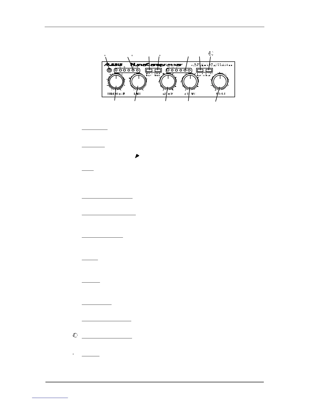
The NanoCompressor’s front panel contains the following:
① Power LED. The Power LED is illuminated whenever the NanoCompressor's
power adapter is plugged in.
➁ Threshold. The Threshold control sets the level above which signals will be
compressed or limited. The range is from -40dB to +8dB, with -10dBu (or 0 VU)
marked with an arrow ( ) near the knob.
➂ Ratio. The Ratio control sets the compression slope, or how much gain reduction
will be done once the signal crosses the threshold level. If the ratio is set for 4:1,
for example, and the input signal is 4dB above the threshold level, the
NanoCompressor will reduce the output level by 3dB.
➃ Gain Reduction Meter. This meter shows how much the compressor is reducing
the input signal.
⑤ Hard/Soft Knee Switch. This controls the character of the compression near the
Threshold level, either hard (abrupt compression above threshold) or soft knee
(gradual transition to compression).
⑥ Peak/RMS Switch. This controls whether the compression will be Peak or RMS
(average) style. When set to RMS, the Attack and Release controls will be
disabled.
⑦ Attack. This is the amount of time it will take for the NanoCompressor to start
compressing when the input signal crosses over the threshold. This control is
disabled when compression is set for RMS.
➇ Release. This is the amount of time it will take for the NanoCompressor to stop
compressing when the input signal crosses under the threshold. This control is
disabled when compression is set for RMS.
➈ Signal Meter. The signal meter can be switched to either monitor the input or the
output. This meter shows the louder of the left or right side.
➉ Input/Output Switch. This switch determines whether the Signal Meter is
displaying the Input or Output level.
Bypass/Comp Switch. This switch allows you to bypass the compressor for an
A/B comparison of the source signal.
Output. This knob sets the output level of the compressor. It is useful for making
up level which has been reduced in the compression process.