4
B
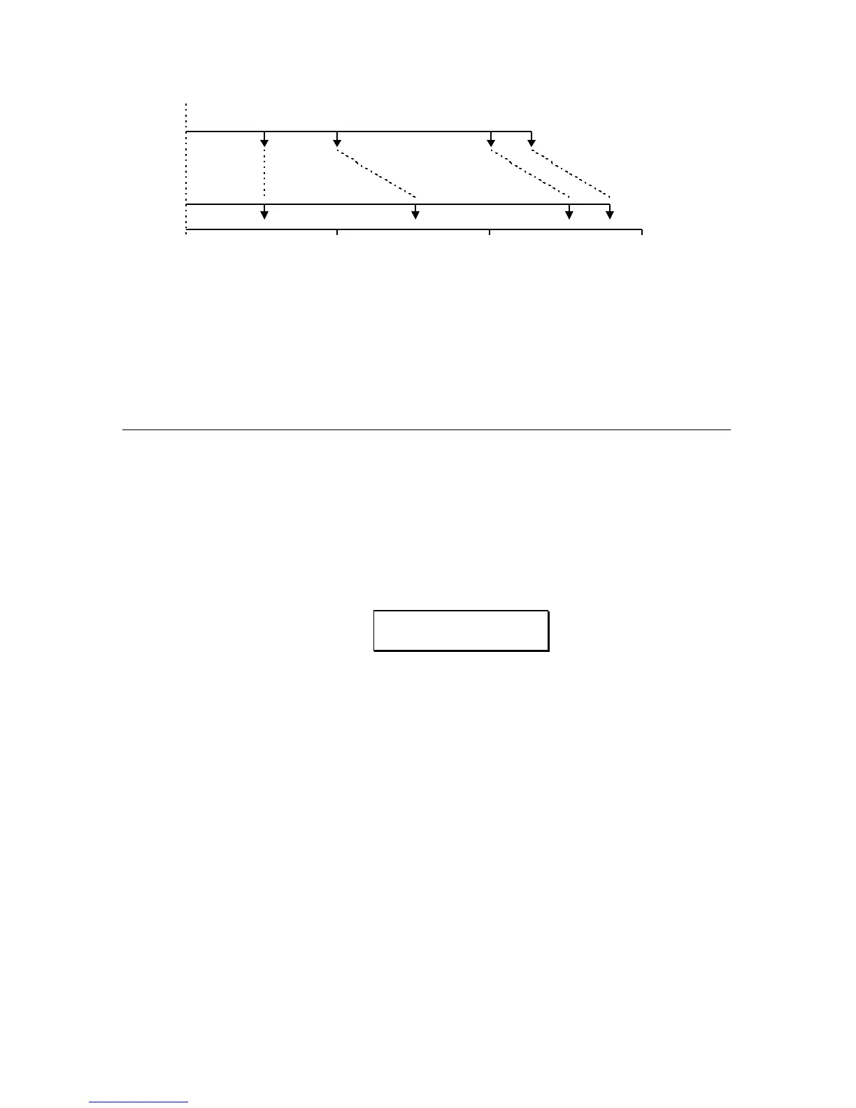
0 0.5 Sec 1.0 Sec 1.5 Sec
TAP 1 TAP 2 TAP 3 TAP 4
250 ms 250 ms 500 ms 125 ms
TAP 1 TAP 2 TAP 3 TAP 4
250 ms 500 ms 500 ms 125 ms
In Figure 7A, Tap #1 is set at 250ms, Tap #2 is set 250ms behind Tap #1
(500ms from the beginning), Tap #3 is set 500ms behind Tap #2 (1 second from
the beginning). In Figure 7B, an additional 250ms is added to Tap #2 which
means that it now occurs at 750ms (instead of 500ms as in 7A), and Tap #3 now
occurs at 1250ms (instead of 1 second in Figure 7A).
SELECTING THE MULTI TAP DELAY
CONFIGURATION
Multi Tap Delay is accessed through the 5 BAND EQ->PITCH->DELAY
configuration.
To select the configuration, first press the
CONFIG button, then press the VALUE
buttons until the display reads:
CONFIGURATION:
5BAND EQ>PCH>DL
The block diagram of this configuration is as follows:
FIGURE 8
5 BAND EQ->PITCH->DELAY BLOCK DIAGRAM (with Multi Tap Delay)