EasyManua.ls Logo

Alfa Laval AC Series - User Manual

Alfa Laval AC Series
26 pages
Print Icon
To Next Page IconTo Next Page
Loading...
Instruction Manual -
Brazed plate heat exchangers
AC, AXP, CB, CD, DOC
EN
3450021401-EN 2017-06
Original manual
Question and Answer IconNeed help?

Do you have a question about the Alfa Laval AC Series and is the answer not in the manual?

Overview

This document provides an instruction manual for Alfa Laval Brazed Plate Heat Exchangers, specifically models AC, AXP, CB, CD, and DOC.

Function Description

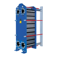
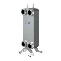
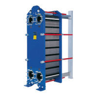
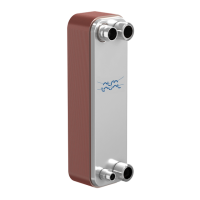
Brazed plate heat exchangers consist of a pack of corrugated metal plates with ports for the passage of two fluids between which heat transfer will take place. The media in the heat transfer are led into the plate pack through portholes at the corners and are distributed into the passages between the corrugated plates. This design facilitates efficient heat exchange between the two fluids.

Important Technical Specifications

The plate heat exchanger is designed to meet the requirement for a wide range of heat transfer applications such as refrigeration, comfort heating, industrial heating and cooling, and process industry. It is crucial to use the plate heat exchanger in accordance with the specified configuration of material, media, temperatures, and pressure for the specific plate heat exchangers.

Name Plates: The mechanical design pressures and temperatures are marked on the name plate. These values must not be exceeded. The unit type, manufacturing number, and year, along with the pressure vessel details in accordance with applicable pressure vessel code, can be found on the name plate. The name plate is fixed to the cover plate (usually on the same side as the connections). Name plate differs depending on the type of pressure vessel approval.

Connection Loads: Maximum recommended connection loads during installation are specified in a table, detailing tension force, bending moment, shear force, and torque for various outer diameter sizes. Shear force (Fs) is calculated assuming that the force is applied at the end of the standard connection.

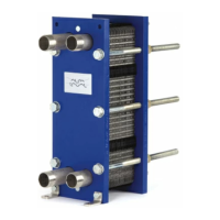
Mounting: The plate heat exchanger can be mounted on the floor, on feet, or on the wall. Larger heat exchangers should be secured with support mountings (ordered as accessory) or by means of mounting bolts. Maximum tightening torques for mounting bolts are provided for different bolt dimensions (M5, M6, M8, M10, UNC 1/4", UNC 5/16", UNC 3/8"). In a rigid pipe system, small heat exchangers can be suspended directly in the pipework. Anti-vibration mounting is recommended to avoid vibrations.

Installation in General: Safety valves must be installed according to pressure vessel regulations. Before connecting any piping, ensure all foreign objects have been flushed out of the system. The installation must be equipped with equipment that protects it against pressures and temperatures outside the approved minimum and maximum values shown on the name plate. For vibration risks, anti-vibration mountings are recommended. The plate heat exchanger is connected so that the media flows through the plate heat exchanger in opposite directions (in counter-current flow) and in most cases this provides the best heat transfer performance. Take into account the risk of fire during installation, especially in the distance from flammable substances.

Connections:

  • Threaded connections: Use a torque wrench when connecting the pipe and observe the specified limits. Refer to the table on page 14 for details.
  • Brazed connections: Clean by rubbing down and degreasing the various surfaces. Use the correct brazing temperature and brazing metal grade.
  • Welded connections: To minimize the heat impact of the heat exchanger, it is recommended to use TIG or MIG welding methods. Preparation for welding: Grind inside and outside of the pipe and, if bevelled, also the bevelled edge at least 25 mm from the pipe edge and inward. This should be done to avoid contamination of copper in the welded area, which might cause the weld to crack.

Installation as Evaporator or Condenser: In applications where a phase change of media occurs, the heat exchanger must be installed vertically. For refrigeration applications, the connections may be either on the front or on the rear.

  • Use an anti-freeze thermostat and flow monitor to ensure a constant water flow before, during, and at least two minutes after the compressor has been running.
  • Avoid "pump-down", i.e., emptying the evaporator by running the compressor after shut-down until a preset refrigerant pressure is reached. The temperature could then drop below the brine freezing point, which could damage the evaporator.
  • Use a flow switch and a low-pressure switch. Make sure only media from the heat exchanger can pass the flow switch. The low-pressure switch should assure a minimum pressure drop of 5 - 10 kPa (0.73 - 1.45 PSI). Heat exchanger with a refrigerant distribution system should be mounted with the distributor at the bottom.

Typical installation of single circuit:

  1. Refrigerant inlet
  2. Refrigerant outlet
  3. Water/Brine inlet
  4. Water/Brine outlet For an evaporator, the pipe should be straight (at least 150 mm / 5.9 inch length) between the expansion valve and refrigerant inlet. Avoid using pipe elbows between the expansion valve and the refrigerant inlet.

Typical installation of dual circuit: A is parallel flow; B is diagonal flow.

  1. Refrigerant inlet
  2. Refrigerant outlet Water/Brine inlet and outlet are typically positioned on the rear side.

Leak Test: Perform leakage test before placing the plate heat exchanger in operation.

Usage Features

Start-up:

  1. Check that the inlet valve (2) is closed between the pump and the unit controlling the system flow rate.
  2. Inlet valve (2, 3) for both fluids should be closed, the outlet valves (1, 4) opened and the vent valve (5, 6) closed.
  3. If there is an outlet valve (4), make sure that it is fully open.
  4. Open the vent valve (5) and start the pump.
  5. Open the inlet valve (2) slowly.
  6. When all air is expelled, close the vent valve (5).
  7. Repeat steps 1–5 for the second media.

Unit in Operation: Adjustments of flow rates should be made slowly in order to avoid the risk of water hammer and to protect the system against sudden and extreme variations of temperature and pressure. During operation, check that:

  • Media temperatures and pressures are within the limits stated on the name plate.
  • No leakages appear due to faulty tightening of the connections.

Protection against connection loads: Ensure the heat exchanger is fastened to avoid or minimize connection loads during operation.

Protection against freezing: Bear in mind the risk of freezing at low temperatures. Plate heat exchangers that are not in operation should be emptied and blown dry whenever there is a risk of freezing. To avoid damage due to freezing, the medium used must include an anti-freeze agent when operating conditions are below 5 °C (41 °F) and/or when the evaporating temperature is below 1 °C (34 °F).

Protection against clogging: Use a filter as protection against the possible occurrence of foreign particles. If you have any doubt concerning the minimum particle size, consult your Alfa Laval Representative.

Protection against thermal or/and pressure fatigue: Sudden temperature and pressure changes could cause fatigue damage to the heat exchanger. Therefore, the following must be taken into consideration to ensure that the heat exchanger operates without fluctuating pressures/temperatures:

  • The plate heat exchanger is not intended for cyclic processes; please contact an Alfa Laval Representative for advice.
  • Locate the temperature sensor as close as possible to the outlet from the heat exchanger.
  • Choose valves and regulation equipment which give stable temperatures/pressures for the heat exchanger.
  • To avoid water hammer, quick-closing valves must not be used, e.g. on/off valves.
  • In automated installations, stopping and starting of the pumps and actuation of valves must be programmed so that the amplitude and frequency of the pressure variation are as low as possible.

Protection against corrosion:

  • Do not use the heat exchanger for de-ionized water as this media can chemically affect the copper brazing material.
  • Do not use the heat exchanger for installations with galvanized pipes that chemically or electrochemically could affect or be affected by the stainless steel plates and the copper brazing material.
  • Copper may generate corrosion in installation with mixed materials.
  • Avoid ammonia or other media that could be corrosive to stainless steel and copper.

Recommended limits for Chloride ions, Cl- at pH 7.5:

Temperature Alloy 304 Alloy 316
at 25 °C / 77 °F 100 ppm 1000 ppm
at 65 °C / 149 °F 50 ppm 200 ppm
at 80 °C / 176 °F 20 ppm 100 ppm

Lower levels of chloride ions may cause corrosion due to other factors. Halogens, e.g. bromides and flourides may also cause corrosion.

Insulation: If the heat exchanger will be operated at very hot or very cold temperature, take protective actions, such as insulation, to avoid injuries. Be certain to follow all local regulations. Heating and cooling insulations are available as accessories. Be aware that temperature limits of insulation and the heat exchanger can be different.

Shut-down:

  1. Slowly reduce the flow rate in order to avoid water hammer.
  2. When the valve is closed, stop the pump.
  3. Repeat steps 1–2 for the other medium/media.
  4. If the plate heat exchanger is shut down for a long period, it should be drained. Also, drain the heat exchanger if the process is shut down and the ambient temperature is below the freezing temperature of the media. Depending on the media processed, rinse and dry the heat exchanger and its connections.

Maintenance Features

General guidelines regarding maintenance: Cleaning can improve the performance of the plate heat exchanger. Cleaning intervals depend on factors such as media and temperatures.

Plate Sheet material: Stainless steel can corrode. Chloride ions are hazardous. Avoid cooling brines containing chloride salts as NaCl and, most harmful, CaCl2.

Chlorine as a growth inhibitor: Chlorine, commonly used as a growth inhibitor in cooling water systems, reduces the corrosion resistance of stainless steels. Chlorine weakens the passive layer of these steels making them more susceptible to corrosion. This is dependent on exposure time and concentration of chlorine. In every case where the chlorination of the plate heat exchanger cannot be avoided, consult an Alfa Laval Representative for advice.

Cleaning-In-Place (CIP): Cleaning-In-Place (CIP) equipment permits cleaning of the plate heat exchanger. CIP performs:

  • By regular CIP, the dissolution of fouling helps to restore the original thermal performance of the unit.
  • The passivating effect by the CIP procedure can help to maintain the original corrosion resistance of the plate material.

Type of cleaning:

  • Acidic cleaning removes inorganic deposits such as limestone.
  • Alkaline cleaning removes organic deposits. During the process it is important to control the pH value and the recommended pH value is 7.5 - 10. Higher pH values increase risk of the copper oxidizing.
  • Neutralization of cleaning liquids before draining and flushing the unit with potable water. Follow the instructions of the CIP equipment. Consult an Alfa Laval Representative for appropriate advice on selecting CIP equipment.

Safety during cleaning:

  • Use proper protective equipment, such as safety boots, safety gloves and eye protection, when using cleaning agents.
  • Corrosive cleaning liquids can cause serious injuries to skin and eyes! For detailed information regarding Cleaning liquids and procedure, refer to the CIP manual. Rinse well with fresh water after cleaning.
  • Make sure that the handling of residuals after using cleaning liquids follows the local environmental regulations.

Fault Tracing:

  • Pressure drop problems:

    • Action 1: Check that all valves are open including non-return valves. Measure the pressure and the flow rate directly in front of the inlet and after the outlet of the heat exchanger. For viscous media use a membrane manometer with a diameter of at least 30 mm. Measure or estimate the flow rate if possible. A bucket and a watch showing seconds may be sufficient for small flow rates. For larger flow rates, use a flowmeter.
      • Correction (YES): -
      • Correction (NO): -
    • Action 2: Compare the pressure drop observed with the specified flow rate (see data printout). Is the pressure drop higher than specified?
      • Correction (YES): Check the temperature program, see step 3.
      • Correction (NO): If the pressure drop corresponds to the specifications, there is no need for action. If the pressure drop is lower than specified, the pump capacity is probably too small or the observation may be wrong. See pump instruction manual.
    • Action 3: Check the thermometer readings. Do the readings correspond to those specified?
      • Correction (YES): The heat transfer surface is probably clean enough, but the inlet to the heat exchanger may be clogged by some objects. Check the port area.
      • Correction (NO): Heat transfer is obviously dropping below specifications, because of deposits on the heat transfer surface, which at the same time also increases the pressure drop, since the passage becomes narrower. If a Cleaning-In-Place (CIP) system is available, follow the instructions and use it to wash out the deposits.
  • Heat transfer problems: The heat transfer capacity is dropping.

    • Action 1: Measure temperatures at inlets and outlets. Also measure flow rates on both media, if possible. On at least one of the media, both temperatures and the flow rate must be measured. Check to see if the transferred amount of heat energy corresponds to the specifications. If great precision is important, it will be necessary to use laboratory thermometers with an accuracy of 0.1 °C, and also to use the best equipment available for flow measurement. Has the heat transfer capacity of the unit dropped below specified values?
      • Correction (YES): Clean the heat transfer surface. Use the Cleaning-In-Place (CIP) system.
      • Correction (NO): -

Alfa Laval AC Series Specifications

General IconGeneral
BrandAlfa Laval
ModelAC Series
CategoryIndustrial Equipment
LanguageEnglish

Related product manuals