3
The sensor is specially build to fit in the plug of the Rotax Max cylinder head water cooling system.
Installing the cylinder head temperature sensor
The sensor is fixed between the cylinder head and the spark plug.
WARNING ! Remove the spark plug washer.
Installing the battery
To change the battery, loosen the two screws on the small cover of the battery holder on the rear of the device. The spent batteries can now
be removed. When inserting new batteries the positive pole (+) must point towards the cover of the battery holder. Then insert the holder into
the housing.
WARNING ! Avoid over-tightening of the screws which could damage the threading. Tighten to the point where both sections of
the housing meet.
Use batteries of the type CR 2450.
A RESET must be carried out every time the batteries are changed (press both push buttons for 2 seconds).
2° MODE OF OPERATION
Switching on :
Press both push buttons simultaneously for 2 seconds. When these are released the display comes on and the system is in the STOP mode.
An unintelligible display can appear while both buttons are being pushed. This is normal. Upon release of the buttons the normal display will
reappear.
This procedure is necessary if the battery has been changed and if the ALFANO jams.
For example: Because of motor disturbances.
Change to START mode :
The ALFANO must first without exception be in the STOP mode. If this is the case then a contact with a magnetic strip is sufficient to
delete the display (small dashes appears).
WARNING ! The word START does not exist in the display.
Return to STOP mode :
Press the left push button (no. 1) or wait 5 minutes after the last contact with a magnetic strip.
Best Time and Highest RPM’s of All Recorded Laps :
In STOP mode only the right button (no. 2) must be activated. The display lasts two seconds.
Within this two seconds you can enter to the Recording Mode “rec”
(see Chapter 5° RECORDING MODE “rec” )
Switching off :
Refrain from activating ALFANO any further, from driving over the magnetic strip, and from running the motor (if the RPM wire is connected).
Wait 10 minutes.
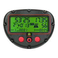
3° DISPLAY (Figure 1)
A LAP TIMER
In the START mode :
The time for each lap is shown, i.e. the time between passing over the same magnetic strip twice. The display is in minutes, seconds
and hundredths of a second as soon as a lap is completed and during the next lap.
In the STOP mode :
The last recorded lap is shown.
In the RECALL mode :
 Loading...