2
www.observint.com
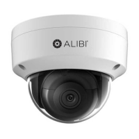
Connect camera drop cables to peripherals, LAN and power
Ethernet connector -
PoE capable
Peripheral interface wire bundle
12 Vdc Power
connector
Camera drop cables to Ethernet, power and peripheral devices
1. Route the camera power and LAN (or LAN with PoE), and peripheral interface wiring for the left and
right audio channels, alarm input and output , and microphone to the camera mounting location (or
into the electrical box).
2. Connect the wires in the peripheral interface wire bundle drop cable to peripheral devices as
needed. See the following table. The camera can connect to two microphones (L and R), an alarm
input sensor and an alarm output (reporting) device, and to two audio line out (L and R) channels.
Label Color Connects to:
LINE_OUT_R Brown Audio line right channel line input. Pair with LINE_GND.
LINE_GND Red Ground for line out left and right channels. Pair with LINE_OUT_L and LINE_OUT_R.
LIN/MIC- Orange Left microphone. Pair with MIC_GND.
RIN/MIC+ Yellow Right microphone. Pair with MIC_GND.
ALARMIN_GND Green Ground for alarm input sensor. Pair with ALARM_IN.
ALARM_IN Blue Alarm input sensor. Pair with ALARMIN_GND.
LINE_OUT_L Violet Audio line left channel line input. Pair with LINE_GND.
MIC_GND Gray (Slate) Ground for microphone left and right channels. Pair with LIN/MIC- and RIN/MIC+.
ALARMOUT_GND White Ground for alarm reporting device. Pair with ALARM_OUT.
ALARM_OUT Black Alarm reporting device. Pair with ALARMOUT_GND.
3. Connect the Ethernet LAN cable to the camera LAN drop cable. Protect the connection from
moisture and other contamination, if necessary. A weatherproof tting is provided.
4. If the camera is not powered using PoE (Power over Ethernet injector), connect the 12 Vdc power
cable to the camera drop cable. The polarity of the drop cable connector is shown below.
CAUTION
Do not apply power to the camera at this time. Before applying power to the camera, ensure that
the polarity is correct. An incorrect connection may cause a malfunction and can damage the
camera.
5. Secure the camera to the mounting surface, or adapter plate, using appropriate screws.
6. Apply power to the camera through the 12 Vdc power cable or PoE injector, as congured.
NOTE: Do not reattach the dome assembly at this time.
Step 2. Install the Alibi Discovery Tool
Alibi Discovery Tool is a software utility used to “discover” Alibi cameras and NVRs/DVRs installed on the
physical Ethernet network (LAN) and change their network settings. Discovery Tool is provided on the CD
with your camera and is contained in Alibi Power Tools. To use Discovery Tool:
1. Insert the software CD provided with your camera into an optical drive on the Microsoft Windows
computer you will use to access your camera on the LAN.
2. On the CD, nd the folder that contains the Alibi Power Tools (Alibi Tools Utility).
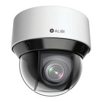
3. Install Alibi Power Tools. Refer to the ALIBI™ Power Tools Installation and User Manual also provided
on the CD. When the program opens, the following screen appears.
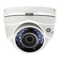
4. Double click on the Discovery Tool icon. The tool will automatically discover Alibi cameras and
recorders installed on the network.
In the example screen shown above, an ALI-NS1024VR camera was discovered. Notice that the IP
address of the camera is 192.168.1.64 (default IP address). This camera, although congured for a
subnet that is probably foreign to the network it is installed on, is still found by the tool.
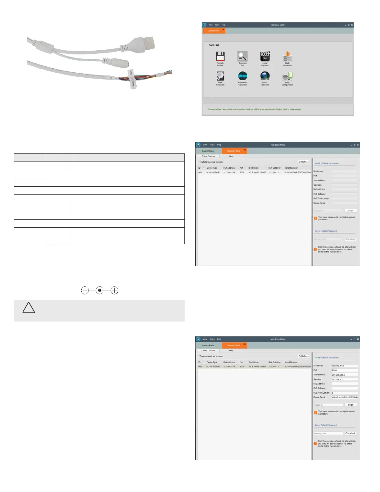
5. To change the network settings of the camera to be compatible with the subnet where it is installed,
do the following:
a. Click on the device to highlight it. Notice that the network parameters for the device populate
the elds in the right frame.
© 2015 Observint Technologies. All rights reserved.