CHAPTER 4: INSTALLING AND REPLACING COMPONENTS
79
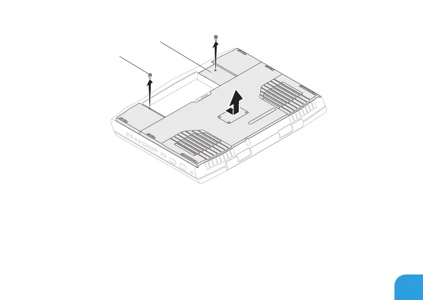
1
2
1 screws (2) 2 compartment door
5. Loosen the three captive screws on the primary hard‑drive assembly (HDD0).
6. Using the pull‑tab, lift the primary hard‑drive assembly to disconnect it from the
connector on the system board.
7. Lift the primary hard‑drive assembly out of the computer base.