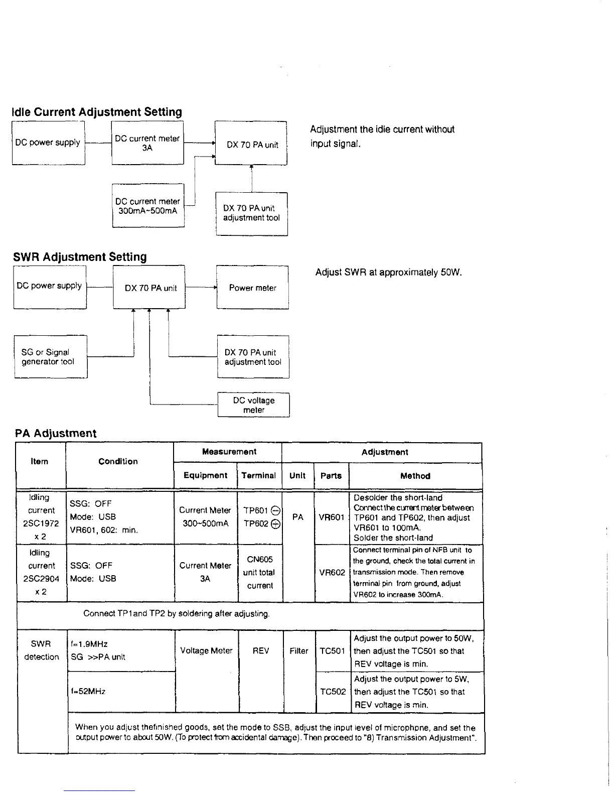
Id le C u rre n t A d ju s tm e n t S etting
Adjustment the idle current without
input signal.
S W R A d ju s tm e n t S e ttin g
Adjust SWR at approximately 50W.
DC voltage
meter
P A A d ju s tm e n t
Item Condition
Measurement
Adjustment
Equipment Terminal
Unit Parts
Method
Idling
current
2SC1972
x 2
SSG: OFF
Mode: USB
VR601, 602: min.
Current Meter
300~500mA
TP601 ©
TP602©
PA
VR601
Desolder the short-land
Connect the current meter between
TP601 and TP602, then adjust
VR601 to 100mA.
Solder the short-land
Idling
current
2SC2904
x 2
SSG: OFF
Mode: USB
Current Meter
3A
CN605
unit total
current
VR602
Connect terminal pin of NFB unit to
the ground, check the total current in
transmission mode. Then remove
terminal pin from ground, adjust
VR602 to increase 300mA,
Connect TP 1 and TP2 by soldering after adjusting,
SWR
detection
f=1,9MHz
SG » P A u n it
Voltage Meter REV Filter
TC501
Adjust the output power to 50W,
then adjust the TC501 so that
REV voltage is min.
f=52MHz
TC502
Adjust the output power to 5W,
then adjust the TC501 so that
REV voltage is min.
When you adjust thefinished goods, set the mode to SSB, adjust the input level of microphpne, and set the
output pcwer to about 50W. (To protect from axidental damage). Then proceed to "8) Transmission Adjustment”.

 Loading...