Do you have a question about the Alinco DR-430 and is the answer not in the manual?
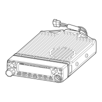
Covers selecting a location and power requirements for mobile installation.
Details DC power supply requirements for fixed base operation.
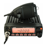
Technical specifications for the DR-130, covering general, transmitter, and receiver details.
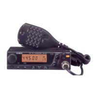
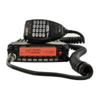
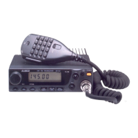
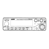
Explains the function of each control and indicator on the front panel of the transceiver.
The main tuning dial allows selection of frequencies, memory channels, offsets, and tones.
Indicates transmission activity with a red light and reception with a green light.
Adjusts the audio output volume by turning the knob clockwise or counterclockwise.
Used to eliminate noise when no signal is present, adjusted to the noise threshold level.
Changes frequency in 1 MHz steps and selects output power with the Func. Key.
Press to turn the unit on, press again to turn it off.
Accesses secondary functions and uses MONI to open squelch for weak signals.
Inverts TX/RX frequencies for repeater mode and selects priority monitoring mode.
Selects sub-audible tone and toggles the lock function on/off with the Func. Key.
Manages Time Out Timer settings and repeater offset direction/step with the Func. Key.
Toggles between VFO and Memory modes; MW writes selections to memory channels.
Accesses pre-programmed call channel or selects channel step for frequency changes.
Connector for the supplied microphone.
Used to connect the antenna to the transceiver with a 50 Ohm impedance.
Connect the supplied power cable to this connector.
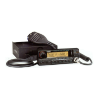
Image and basic description of the microphone included with the unit.
Step through VFO, memory channels, offsets, and tones; initiates timer scan when held.
The unit transmits when the Push-To-Talk key is depressed.
Indicates the function key is active and secondary functions can be accessed.
Indicates CTCSS tone is encoded; tone is transmitted with the main carrier.
Indicates CTCSS tone decoding is active for selective listening.
Indicates upward transmitter offset in Duplex mode.
Indicates downward transmitter offset in Duplex mode.
Indicates low power transmission; transmission is in high power when display is off.
Displays selected transmit/receive frequencies, channel step, Time Out Timer, or sub-audible tone frequencies.
Indicates that the Memory Mode is active.
Indicates the selected memory channel number.
Indicates signal reception and open squelch.
Indicates relative received or transmitted signal strength for reference.
Explains the operation of VFO, Memory, and Call modes for frequency selection and storage.
Describes how to select and set CTCSS tones for selective reception and transmission.
Details the two scanning modes: VFO scan and Memory scan, including how to start and stop.
Explains the Priority feature for monitoring a secondary channel while operating on a primary channel.
Explains how to activate and deactivate the Key Lock function to prevent accidental key presses.
Details how to select the shift direction (+ or -) and set the repeater offset value.
Instructions for recalling, writing, and clearing memory channels, including memory recall and write.
Explains how to select the channel step for VFO frequency tuning from six selectable options.
Describes how to select between high and low transmit power levels.
Explains how to enable, transmit, and disable the 1750 Hz Tone Burst feature.
Covers additional features like Time Out Timer, Reverse, Open Squelch, Beep, and Reset.
Explains the Time Out Timer function, which limits excessive transmit time.
Explains the Reverse function for inverting transmit and receive frequencies for repeater or simplex operation.
How to open the squelch to monitor weak signals by pressing the Func key.
Instructions for disabling or enabling the beep tone by holding specific keys while powering on.
Instructions for resetting the unit to factory default settings, which erases all memory channels.
| Brand | Alinco |
|---|---|
| Model | DR-430 |
| Category | Transceiver |
| Language | English |