75.5739.04 ALLEGION 8310-836 20201103 Page 3 of 475.5739.04 ALLEGION 8310-836 20201103 Page 3 of 4
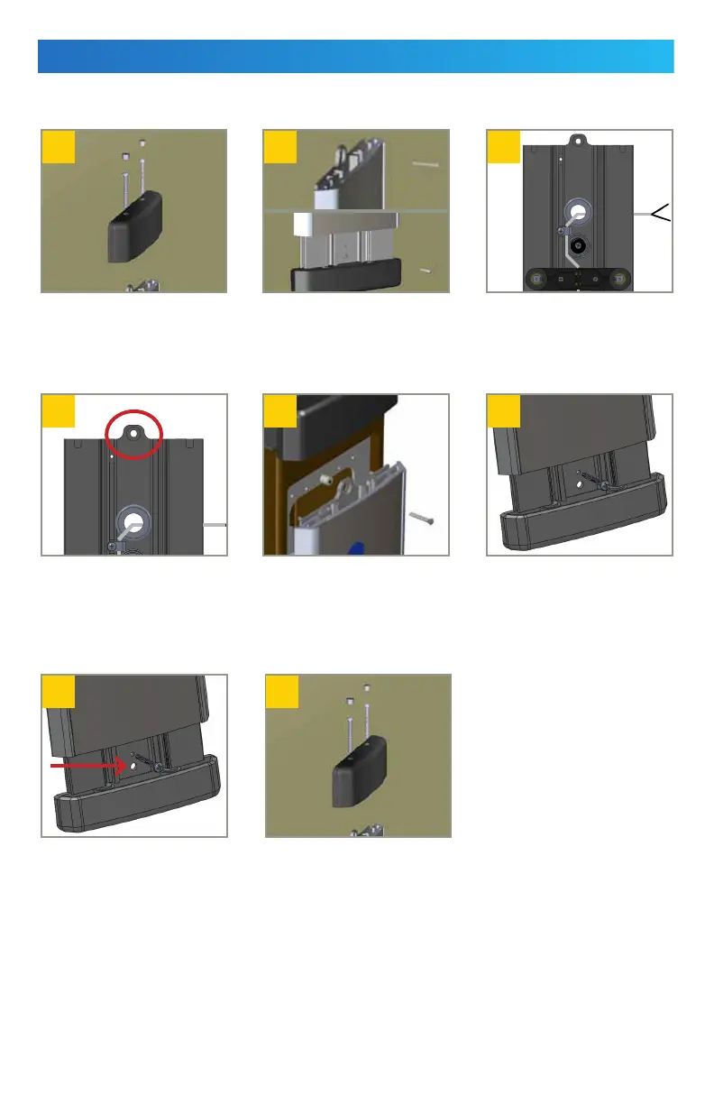
MOUNTING
Do not remove the face plate during mounting.
1 2 3
5 6
7 8
4
NOTES:
1. If installing a wireless version, allow the top end cap assembly to hang loosely by the cable during set-up. Do not unwire.
2. Image shown has the plate and end cap removed for illustration purposes.
3. To avoid activation issues, do not push excess wire(s) into the plate assembly during reassembly.
Remove the top end cap by
removing its screw covers and
then removing the screws.
After removing the top end
cap, remove the top and
bottom locking hole screws.
1
To complete a wireless set-up
(or change the battery), refer
to User’s Guide 75.5315.
To mount to a bollard, attach
the switch to the bollard using
a 10-24 × 0.75 mounting screw
and nylon spacer.
To secure the bottom plate
assembly, first slide the front
plate upwards, and then insert
a top end cap screw into the
threshold to hold.
Secure the plate assembly using
the bottom mounting screw.
Remove the top end screw from
base and slide down.
Replace the top end cap with
provided screws and reinstall
the screw covers.
Make necessary wiring
connections.
2
Ensure excess
wiring is kept inside the
junction box, if used.
3
Install an appropriate anchor
through the top mounting
hole.
 Loading...