Do you have a question about the Allegion Schlage L-Series and is the answer not in the manual?
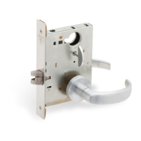
| Series | L-Series |
|---|---|
| Type | Mortise Lock |
| Brand | Schlage |
| Manufacturer | Allegion |
| Function | Entry, Privacy, Passage |
| Backset | 2-3/4 in. |
| Door Thickness | 1-3/4 inches to 2-1/4 inches |
| Handing | Reversible |
| Security | High Security (depending on cylinder) |
| ANSI Standard | ANSI/BHMA A156.13 |
| Standards | Meets or exceeds BHMA standards |
| UL Listing | UL10C |
| Keyway | Schlage C Keyway |
| Warranty | Limited lifetime mechanical and finish warranty |
Details on certifications, case size, armor front, deadbolt, latchbolt, strike, backset, cylinder, door range, and keys.
Highlights new features for electrified locks, multipoint locks, and indicator options.
Index of various lock functions with descriptions, ANSI specifications, and page references.
Exploded view and parts list for L400-Series deadbolt trims.
Exploded view and parts list for double cylinder trims.
Exploded view and parts list for electrified trims with both sides locked/unlocked.
Exploded view and parts list for L400 series assembled lock cases.
Exploded view and parts list for L9000 series assembled lock cases.
Exploded view and parts list for L9080EL and L9080EL-RX electrified lock cases.
Exploded view and parts list for L9493 EL/EU and L9495 EL/EU electrified lock cases.
Illustrates the assembly of turn hub spring and transfer lever.
Details on extended mortise cylinders and IC cylinders for various lock functions.
Contents of the 40-054 maintenance kit for lock case parts.
Illustrations and descriptions of different armor front types and their functions.
Details strike dimensions, lip types, lock series, door range, strike box, and screws.
Table detailing cylinder requirements based on function, trim, and door thickness.
Details on SFIC cylinders, including Everest and construction cores.
Overview of EL (fail safe) and EU (fail secure) modes for electrified locks.
Information on Deadbolt Monitor (DM) function for electrified locks.
Details on available armor fronts for LM9200 Series two-point locks.
Lubrication points for L9000 and LM9300 Series lock cases and subassemblies.
Lubrication points for LM9200 Series lock cases and subassemblies.
Step-by-step instructions for changing the lock hand orientation.
Guide on the sequence and data required for ordering Schlage products.
List of available finish codes and their descriptions according to BHMA.
Details the 3-year limited warranty for commercial products.
Installation steps for L9000-Series locks with lever and rose trim.
Instruction for adjusting the handing screw for L and LV locks.
Installation steps for L9000-Series locks with knob and rose trim.
Installation overview for L400 Series small case mortise locks.
Initial step for installing L400-Series lock chassis.
Instructions for installing the outside cylinder with indicator trim.
Details on available indicator trim options for escutcheon.
Crucial step to check lock handing before installing indicator trim.
Procedure for installing the outside indicator trim components.
Procedure for installing the inside indicator trim components.
Crucial step to check lock handing before installing indicator trim.
Guidance on door preparation for indicator trim installation.
Installation steps for indicator trim with turn or cylinder.
Overview of EL (fail safe) and EU (fail secure) modes for electrified locks.
Information on Latchbolt Monitor (LX) function for electrified locks.