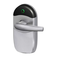
7. Furniture Installation
• While holding the snib lever
horizontally place the interior and
exterior handle assemblies over the
lockbody.
• Ensure that the square drives on the
lever and snib lever are guided into
the lockbody.
• Secure the handle assembiles with
two #8x 32mm handle assembly
screws.
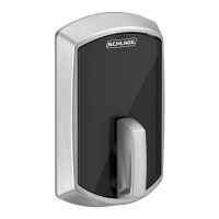
6. Snib Lever & Plug Assembly
vertical
Interior Handle
Assembly
(in this example)
Exterior Handle
Assembly
(in this example)
snib
lever
snib
plug
• Hold the snib lever vertically and insert
it into the snib lever hole in the interior
handle assembly.
• Turn the snib lever until horizontal to
secure it.
• Fit the snib plug in behind the snib
hole cover of the exterior handle
assembly.
snib hole cover
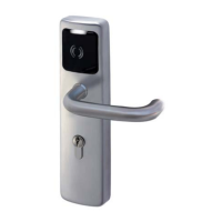
4. Interior Furniture Preparation
• Select the interior handle assembly
to suit your door, then punch out
the snib hole cover.
NOTE: Punch out from the FRONT.
5. Snib Lever Selection
Push down
• Break the snib lever pair in two.
TIP : Put the pair on a flat surface and
push down on the middle.
interior
plate A
interior
plate B
snib
lever A
snib
lever B
• Select the correct snib lever according
to the diagram below
lockbody
sticker
rear slide
1. Lockbody preparation
• If the sticker has been broken or
removed,ensure that the rear slide
• The sticker on the rear of the lockbody
is to assist in easy installation. - Do not
remove.
• If the sticker
has been
broken or
removed,en-
sure that the
rear slide is
pushed
completely
down before
assembling the
lockbody into
the door
cutout.
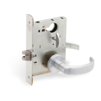
2. Lockbody installation
156mm
16mm
Door Cutout
Door preparation
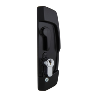
3. Cylinder Installation
cylinder
screw
beak
cam operation
cylinder
cylinder cam
• Insert the key and turn to locked position.
• Insert #10 x38mm cylinder screw & tighten.
NOTE: test, beak should not depress.
• Assemble the cylinder through the lock so the
cylinder protrudes equally from both sides.
NOTE: the cylinder cam must rotate as shown
below. (cam turns towards front of door)
• Turn key to unlocked position and remove
key.
lever - square
drive
handle
assembly
screw
IMPORTANT: If installing SD7 with a
multipoint accessory kit, be sure to follow
the cylinder installation procedure within
the multipoint kit instructions.
• Insert the lockbody into the door
cutout
• Secure the lockbody with two
#8x13mm lockbody screws
SD7 Sliding Security Door
Lock Installation Instructions
lockbody
door cutout
lockbody screws