The provided manual details the service and maintenance procedures for the Allen & Heath AR84 and AR2412 audio rack units. These devices function as remote I/O (input/output) expanders for digital mixing systems, specifically designed to extend the number of available audio inputs and outputs at a remote location, connecting back to a main mixer unit via a digital audio network.
Function Description
The AR84 and AR2412 are essential components in a professional audio setup, acting as a bridge between analog audio sources (like microphones and instruments) and a digital mixing console. They convert analog audio signals into a digital format for transmission over a network, and conversely, convert digital audio signals from the mixer back into analog for output to loudspeakers or other analog devices.
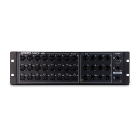
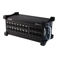
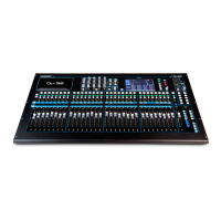
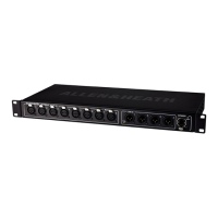
The AR84, as suggested by its name, typically offers 8 analog inputs and 4 analog outputs, providing a compact solution for smaller remote I/O needs. The AR2412, a larger unit, offers 24 analog inputs and 12 analog outputs, catering to more extensive stage or studio requirements. Both units are designed for robust performance in demanding live sound or studio environments.
Their primary function is to simplify cabling and improve signal integrity by digitizing audio close to the source. Instead of running numerous long analog cables, a single digital network cable (often Cat5e or Cat6) can carry multiple channels of audio data, reducing clutter, potential for interference, and signal degradation over distance. This makes setup quicker and more efficient, especially in complex productions.
The units integrate seamlessly with Allen & Heath's digital mixing systems, utilizing proprietary digital audio networking protocols (such as dSNAKE, as indicated by labels on the AR2412). This ensures low latency, high-quality audio transmission, and reliable control communication between the rack and the main mixer. The "EXPANDER" and "MONITOR" labels on the AR2412 suggest dedicated connections for expanding the system further or for local monitoring purposes, enhancing flexibility in system design.
Usage Features
The AR84 and AR2412 are designed for straightforward integration and operation within an Allen & Heath ecosystem.
- Connectivity: They feature multiple XLR input and output connectors for connecting microphones, line-level sources, and sending audio to various destinations. The RJ45 connectors are crucial for the digital audio network connection, allowing the units to communicate with the main mixer.
- Status Indicators: The presence of "Lnk/Err" (Link/Error) LEDs on the RJ45 ports provides immediate visual feedback on the network connection status. A steady "Link" light indicates a successful connection, while an "Error" light would signal a problem, aiding in quick troubleshooting during setup or performance. The manual also mentions a "Ready LED" which, although fitted to all I/O PCBs, is noted as not being used on certain outputs and is bent up inside the chassis, suggesting it might be a universal component for various models, with specific functionality enabled or disabled depending on the unit's configuration.
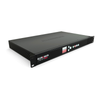
- Rack-Mountable Design: Both units are designed to be rack-mounted, which is standard practice in professional audio. This allows for secure installation in equipment racks, protecting them from physical damage and keeping the setup organized. The images show mounting ears with screw holes, confirming their rack-mountable form factor.
- Power Supply: The units require external power, and the manual emphasizes connecting them to the correct mains power type as described in the user guide and marked on the rear panel. This is crucial for safe and reliable operation.
Maintenance Features
The manual is primarily a service guide, focusing heavily on the maintenance and repair aspects of the AR84 and AR2412. This indicates that the devices are designed to be serviceable, allowing technicians to diagnose and replace components rather than requiring full unit replacement for many issues.
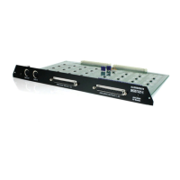
- Modular Design: The internal layout, as shown in the images, suggests a modular design with PCBs (Printed Circuit Boards) that can be accessed and replaced. This simplifies repairs, as a faulty board can be swapped out, reducing downtime. The "IDR Rack Comms PCB" is a key component that can be removed and re-installed, highlighting this modularity.
- Component Access: The manual provides step-by-step instructions for gaining access to internal components. This includes removing the top cover by unscrewing multiple fasteners, and then carefully detaching specific PCBs. The process involves removing RJ45 clips and screws, as well as PCB mounting screws, to free the communication boards.
- Cable Management: The presence of cable ties and instructions on how to place them over mounting pillars during re-assembly indicates attention to internal cable management, which is important for preventing damage to wires and ensuring proper airflow.
- Connector Disconnection: Instructions for disconnecting internal harnesses (like the DC harness) and connectors are provided, ensuring that technicians can safely and correctly isolate components during repair.
- ESD Precautions (Implied): While not explicitly stated in the provided snippets, the nature of working with electronic PCBs implies the need for electrostatic discharge (ESD) precautions, which would typically be covered in a comprehensive service manual to prevent damage to sensitive components.
- Tooling: The manual shows common tools used for maintenance, such as screwdrivers and pliers, indicating that standard workshop tools are sufficient for most service tasks. The use of cardboard to protect paint during clip removal demonstrates practical tips for maintaining the aesthetic condition of the unit during service.
- Documentation: The manual itself is a critical maintenance feature, providing detailed visual guides and instructions for disassembly and re-assembly. It also mentions the availability of a "Parts Identification document" and the non-publication of schematics for digital audio and control circuitry, guiding technicians on what information is available for repair.
- Warranty and Service Policy: The "Limited One Year Warranty" section outlines the conditions for warranty service, emphasizing proper installation, operation, and the requirement for repairs to be carried out by authorized personnel. This ensures that maintenance is performed to a professional standard, preserving the integrity of the device.
- Safety Precautions: The "Servicing Precautions – General Notes" section is paramount for maintenance, covering aspects like qualified service personnel, safe work environments, mains power handling (including isolation transformers and correct fuse replacement), and careful handling during opening and closing the unit. These precautions are vital for the safety of the technician and the longevity of the equipment.