Do you have a question about the ALLEN & HEATH GS-R24 and is the answer not in the manual?
Details the terms and conditions under which the warranty is valid, including proper installation and use.
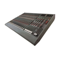
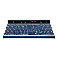
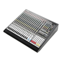
Provides a comprehensive overview of the GS-R24 mixer's design philosophy, features, and capabilities.
Details the various input and output connectors located on the rear panel of the mono input channel.
Explains the function of each control and switch on the front panel of the mono input channel.
Discusses the high-quality pre-amplifier design, its heritage, and performance characteristics.
Describes the High Frequency equalization section, its corner frequency, and boost/cut range.
Details the High Mid Frequency equalizer, sweepable center frequencies, and Q factor.
Explains the Low Mid Frequency equalization, center frequencies, and Q factor variability.
Describes the Low Frequency equalization, corner frequency, and boost/cut range.
Explains the function of the EQ IN switch, which bypasses or engages the equalizer section.
Details how Aux sends 1 & 2 function, their pre-fade nature, and mute switch interaction.
Explains that Aux sends 3 & 4 are normally post-fader but can be pre-fader.
Describes Aux sends 5 & 6 as post-fader by default, commonly used for effects.
Explains the pan control's function in balancing signal between left/right and group buses.
Describes switches for routing signals to L-R, Mono, and Group buses.
Details switches A, B, C, D that configure interface send and return paths.
Explains the channel mute function, its LED indicator, and soft mute circuit.
Describes the multi-functional Solo/Select switch for soloing, PFL/AFL, and MIDI control.
Details the 100mm fader for channel level control and its MIDI controller capabilities.
Details the RCA and Jack sockets for stereo inputs on the rear panel.
Explains the level controls and routing switch for Stereo Input Channels.
Describes the high-frequency equalization for stereo channels, including corner frequency and range.
Details the High Mid and Low Mid fixed bandpass EQ sections for stereo channels.
Explains the low-frequency shelving EQ for stereo channels, its corner frequency, and range.
Explains the function of the EQ IN switch for engaging or bypassing the stereo channel EQ.
Details stereo aux sends, their pre-fade nature, and mute switch behavior.
Explains that stereo aux sends 3 & 4 are normally post-fader but can be pre-fader.
Describes stereo aux sends 5 & 6 as post-fader by default, used for effects.
Explains the balance control for adjusting stereo signal distribution to mix buses.
Describes routing switches for stereo channels to L-R, Mono, and Group buses.
Details switches for determining the source for stereo interface sends and returns.
Explains the mute function for stereo channels and its LED indicator.
Describes the multi-functional Solo/Select switch for stereo channels.
Details the 100mm stereo fader for level control, noting it's not MIDI enabled.
Details the connectors for the valve input channel on the rear panel.
Explains the I/P=DAW, Line/Instrument, Phantom Power, Boost, and Polarity controls.
Explains the gain adjustment for the valve input channel, noting its behavior with DAW input.
Details the Drive control for valve stage saturation and its LED indicator.
Explains the fader-like level control for the valve channel.
Explains the pan control for the valve channel.
Describes routing switches for the valve channel to mix buses.
Explains the AFL switch for the valve channel's post-level signal.
Details the jack sockets for auxiliary bus output signals on the rear panel.
Explains the level and AFL controls for the auxiliary master outputs.
Details the jack sockets and insert points for group bus outputs on the rear panel.
Explains the routing switches, pan, meter, mute, AFL, and fader controls for group buses.
Details the jack sockets for studio artist feed outputs on the rear panel.
Explains the level and stereo controls for various studio output submixes.
Details various connectors for main outputs, monitors, and 2-track inputs on the rear panel.
Explains various controls in the master section including meters, talkback, headphones, and monitor sources.
Explains the PFL mode for monitoring pre-fade signals and its interaction with other modes.
Explains the AFL mode for monitoring post-fade signals and its interaction with other modes.
Describes the Solo in Place mode where pressing a solo switch mutes other channels.
Explains that when neither PFL/AFL is selected, Solo switches act as MIDI select buttons.
Explains that in ADD mode, multiple solo switches can be selected simultaneously.
Explains the function of the Solo Clear switch.
Details how this switch re-routes interface sends to Aux 1-4 and group outputs.
Explains how this switch enables 5.1 surround monitoring from DAW interface returns.
Describes the VU meters for monitoring the master stereo bus level.
Explains the LEDs indicating the status of the Solo in Place system.
Describes the LED meter for the valve input channel pre-fade signal.
Describes the LED meter for the stereo input channel pre-fade signal.
Describes the LED meter for the mono input channel pre-fade signal.
Explains how Solo/Select switches function as MIDI select buttons in SEL mode.
Details how fader mode switches configure MIDI-enabled channel faders.
Describes the two 60mm faders for assigning DAW parameters via MIDI.
Explains the twelve rotary potentiometers for controlling DAW parameters via MIDI.
Details the five switches for transport control of DAWs or hardware devices.
Describes the fourteen switches for assigning and controlling DAW parameters via MIDI.
Explains the jogwheel for scrolling or increment/decrement functions via MIDI.
Notes the mono master fader can be used as a MIDI control fader.
Provides the default MIDI data messages unique to GS-R24 for mapping in DAW software.
Explains how to set console operational modes by holding PLAY and pressing SEL buttons.
Details how to set the MIDI channel number by holding REC and pressing SEL buttons.
Illustrates a workflow for recording direct from the pre-amp with direct monitoring/mixing.
Illustrates a workflow for recording direct from the EQ with direct monitoring/mixing.
Illustrates a workflow for insert processing by DAW or direct recording with EQ on monitor.
Illustrates a workflow for recording direct from EQ with DAW track monitoring.
Illustrates a workflow for mixing in a DAW using the fader as a controller.
Illustrates a workflow for analogue summing mixdown from DAW tracks using automated fades.
Illustrates a workflow for over-dubbing/recording from pre-amp, monitoring DAW output.
Illustrates a workflow using analogue insert and EQ on a digital track.
Details internal jumper settings for mono input channel options and aux sources.
Details internal jumper settings for stereo input channel options and aux sources.
Illustrates the correct wiring for insert cables, distinguishing send and return.
Provides general wiring guides for various cable types like Y-adapters, TRS, and XLR.
Instructions and information for registering the product to ensure warranty service.
| Channels | 24 |
|---|---|
| Microphone Preamps | 24 |
| Line Inputs | 24 |
| Inputs | 24 |
| Outputs | 20 |
| EQ | 4-band EQ with sweepable mid |
| Aux Sends | 6 |
| Faders | 100mm |
| Metering | LED metering |
| Type | Analog Mixing Console |
| Digital Interface | FireWire |
| Computer Connectivity | FireWire |
| Control Surface | Yes |
| Connectivity | FireWire, MIDI |
| Weight | 34 kg (75 lbs) |