Allen & Heath 23 GS_R24 User Guide
GROUP BUS OUTPUTS & MASTER CONTROLS.
L-R
PAN
L R
=
M
PK!
+6
0
SIG
1
MUTE
AFL
L-R
PAN
L R
=
M
PK!
+6
0
SIG
1
MUTE
AFL
L-R
PAN
L R
=
M
PK!
+6
0
SIG
1
MUTE
AFL
L-R
PAN
L R
=
M
PK!
+6
0
SIG
1
MUTE
AFL
10
0
10
20
30
40
10
0
10
20
30
40
10
0
10
20
30
40
10
0
10
20
30
40
REAR PANEL CONNECTIONS
FRONT PANEL CONTROLS
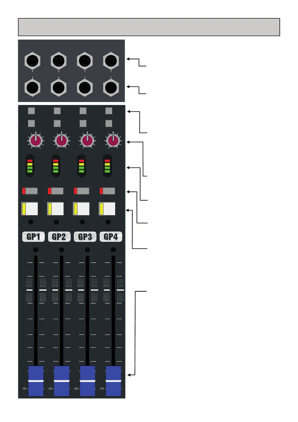
Group bus Output Jack Socket
Standard 1/4” (6.25mm) Jack sockets for Aux bus output sig-
nals. Wired Tip=Hot(+), Ring=Cold(-), Sleeve=Chassis. Nomi-
nal level is +4dBu. Electronically balanced.
Insert Jack Socket
Standard 1/4” (6.25mm) Jack socket for unbalanced insert send
and return signals. Wired Tip=send, Ring=return,
Sleeve=Chassis. Nominal level is –2dBu.
Group bus sub routing to L-R switch
Routes the post fade group signal to the main L-R mix bus via
the pan control.
Group bus sub routing to M switch
Routes the post fade group signal to the main mono mix bus.
Group pan control
Adjusts the amount of level that is shared between the left &
right mix buses.
Group meter
Shows the level of the audio signal post-fade.
Group mute
A direct switched mute for the group output and sub routing.
Group AFL
An After Fade Listen switch to select the post fade (pre-mute)
group signal to the AFL monitoring system.
A full description of the monitoring system is given on page
29.
Group Fader
A 100mm fader positioned after the insert point in the signal
path, controls the overall level of the group signal to the out-
put, sub routing, and monitor signal. The fader has 10dB gain
at the top of its travel.
GRP 1
INSERT
OUT
GRP
2
INSERT
OUT
GRP
3
INSERT
OUT
GRP
4
INSERT
OUT
Serial No.
 Loading...