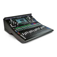
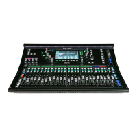
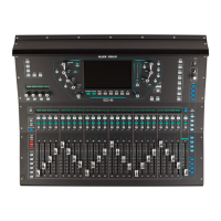
Do you have a question about the ALLEN & HEATH SQ and is the answer not in the manual?
Instructions for accessing the unit's interior by removing the bottom panel.
Steps to disconnect and remove fans, including unclipping connections.
Explanation of the dedicated 12-volt supply for fader motors and its regulation.
Guidance on removing and testing individual fader PCBs and motors.
Reference for connecting fader motors, including wire reuse guidelines.
Information on the two separate cables for TFT screen touch and display.
Guidance on mounting the screen, reusing components, and handling adhesive pads.
Details on LCD PCBs and how issues on one can affect others.
Notes on the LCD bezel's material and potential issues during mounting.
Schematic illustrating power flow between different components of the SQ unit.
Diagram detailing audio, control, USB, and Ethernet signal paths.
Explanation of the 4-channel LCD screens and their control signals.
Information on using LEDs, power rails, and routing overviews for diagnostics.
Explanation of LEDs on the CPU board and their diagnostic meanings.
Explanation of LEDs on the DSP FX board and their diagnostic meanings.
Explanation of LEDs on the Fader board and their diagnostic meanings.
Instructions for testing the 5V supply for fader motors using specific test points.
Instructions for clearing mix settings and saved data by holding specific keys.
Steps for reinstalling firmware using a USB drive and specific key combinations.
| Type | Digital Mixer |
|---|---|
| Channels | 48 |
| Effects | 8 stereo FX engines |
| Talkback | Yes |
| Sampling Rate | 96kHz |
| Expandable Channels | Up to 48 local + 48 remote |
| Local Outputs | 16 |
| Digital Outputs | AES3 |
| EQ Bands | 4-band parametric |
| Effects Racks | 4 |
| Connectivity | Ethernet, USB |
| USB Audio Interface | 32x32 |
| Built-in Interfaces | SLink |
| Screen | 7-inch touchscreen |
| Software | SQ MixPad |
| Power Supply | Internal |
| Weight | 10.5 kg |
