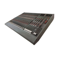
Allen & Heath 22 GS_R24 User Guide
AUXILIARY MASTER OUTPUTS & CONTROLS
AUX1
AFL
AUX3
+6
0
+6
0
+6
0
AUX2 AUX4
+6
0
AUX5
+6
0
AUX6
+6
0
AFLAFLAFLAFLAFL
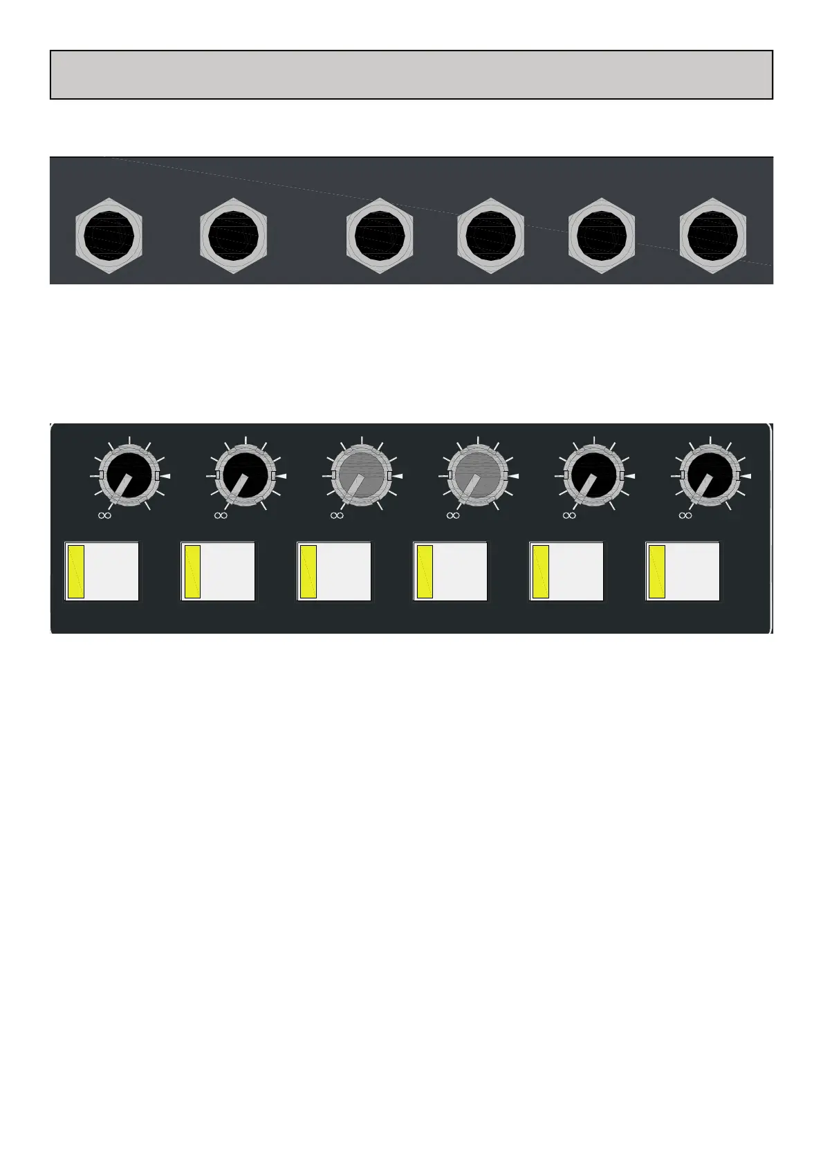
Aux master level control
Each of the 6 auxiliary buses has a master level control to adjust the overall level of the aux summed mix to the output. The
range is from fully attenuated to +6dB gain.
REAR PANEL CONNECTIONS
FRONT PANEL CONTROLS
Aux bus Output Jack Socket
Standard 1/4” (6.25mm) Jack sockets for Aux bus output signals. Wired Tip=Hot(+), Ring=Cold(0V), Sleeve=Chassis. Nominal
level is 0dBu.
Aux master AFL
An After Fade Listen switch is provided to switch the post level control aux signal to the AFL monitoring system.
A full description of the monitoring system is given on page 29.
AUX
1
AUX
2
AUX
3
AUX
4
AUX
5
AUX
6
 Loading...