5–2 Part Replacement Procedures
Publication 1336 IMPACT-6.2 – March 1998
Electrostatic discharge generated by static electricity can damage the
complementary metallic oxide semiconductor devices on various
drive boards. It is recommended that you perform these procedures
to guard against this type of damage when circuit boards are
removed or installed:
• Wear a wrist-type grounding strap that is grounded to the chassis.
• Attach the wrist strap before removing the new circuit board from
the conductive packet.
• Remove boards from the drive and immediately insert them into
their conductive packets.
Tools
You need the following tools to disassemble and assemble the drive:
• Pliers
• Phillips screwdriver
• Standard screwdriver
• 5/16-inch or 8 mm socket
• 11/16-inch or 17 mm socket
• 5/16-inch or 8 mm open-end wrench
• Torque wrench, metered in lb-in. or N-m
This section explains in detail how to replace the following drive
components:
• Ground Sense CT
• Bus Fuse F1
• Thermistor
• Power Modules PM1 – PM3
• Input Rectifier SCR1
• Fan
• DC Bus Inductor L1
• Bus Capacitors
For Gate Driver Board, Main Control Board, Precharge Board, and
L Option Board installation and removal procedures, refer to
Chapter 3.
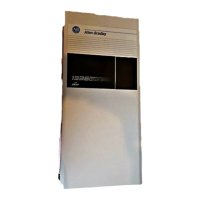
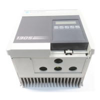
Rockwell Automation Adjustable Frequency AC Drives are modular
by design to enhance troubleshooting and spare parts replacement,
thereby helping reduce production down-time.
Major Component
Replacement
Detailed Product
Identification
AB Spares

 Loading...


