2-6 Malfunctions with Indications
Fault Status Indicators
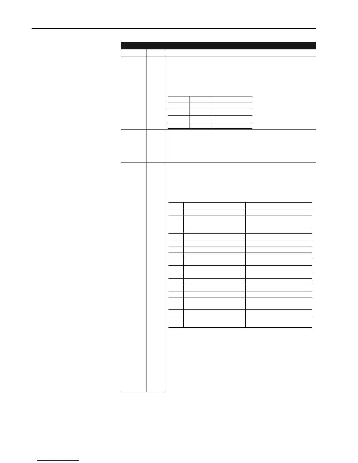
Parameter Name Description
100 Logic
Status
Parameter 100 uses bits 0 and 1 to indicate the highest priority fault level
present in the drive. The two bits are binary coded to allow for four
different indications. This source configuration parameter can be linked to
various adapters depending on the application. It can also be monitored
by the Programming Terminal.
101 Drive
Fault
Parameter 101 is a bit coded source configuration parameter that can
report the status of Soft and Warning Faults that exist in either the Current
Processor or Velocity Processor. The selection between Current
Processor or Velocity Processor faults is made in the setup parameter 630
“Fault Report”.
630 Fault
Report
Parameter 630 is a setup parameter which determines whether the
Current or Velocity Processor faults will be reported. If parameter 630 = 0,
then Current Processor faults will be reported in parameter 101. If
parameter 630 = 1, then Velocity Processor faults will be reported in
parameter 101. The corresponding bit definitions can be found below.
Bit 1 Bit 0 Definition
0 0 No Fault
0 1 Warning Fault
1 0 Soft Fault
1 1 Hard Fault
Bit Fault Definition(630=0) Fault Definition(630=1)
0 CP-06 Phase Loss VP-10 Feedback Loss
1 CP-05 Logic Power Supply ECOAST Status (0=Closed,
1=Open)
(1)
(1)
Bit 1 ECOAST Status is not a fault indicator but does allow the operator to
monitor, through a source configuration parameter, whether the ECOAST circuit
is closed. The ECOAST string allows the drive to close the DC contactor. If the
string is closed bit 1 will be set to 0 and the DC contactor will be allowed to close
if commanded. If the circuit is open then bit 1 will be set to 1 and the DC
contactor will be held open.
2 CP-08 AC Overcurrent Trip VP-12 Absolute Overspeed
3 CP-09 DC Fault (Overcurrent) VP-13 Motor Field Tolerance
4 CP-07 Overcurrent Trip (AC/DC) VP-14 SCR Overtemp
5 VP-31 Arm Bridge Overload Trip VP-15 External Overtemp
6 VP-32 Motor Field Loss VP-16 Thermal Overload Pending
7 Defined for internal use only VP-17 Thermal Overload Tripped
8 VP-34 Waiting Safe Arm Voltage VP-18 Motor Stalled
9 VP-35 Waiting Zero Arm Current VP-19 Contactor Failure
10 Excessive Arm Voltage Demand VP-20 AC Voltage
11 Defined for internal use only VP-21 VP Handshake with SP
12 Defined for internal use only VP-22 VP Handshake with CP
13 VP-39 Arm Bridge Overload Pend VP-23 SP Mode Request Not
Honored
14 Not Used VP-24 CP Not in VP Requested Mode
15
(2)
Status of Param 630 “Fault Report” Status of Parameter 630 “Fault
Report”
(2)
Bit 15 in either selection reflects the present status of parameter 630
“FaultReport”. If bit 15 is 0 then the Current Processor Fault status is being
reflected in parameter 101. If bit 15 is 1 then the Velocity Processor Fault Status
is bein
reflected.
Aotewell Ltd industry-mall.net
 Loading...


