6-4 Test Points
Power Stage Interface Board
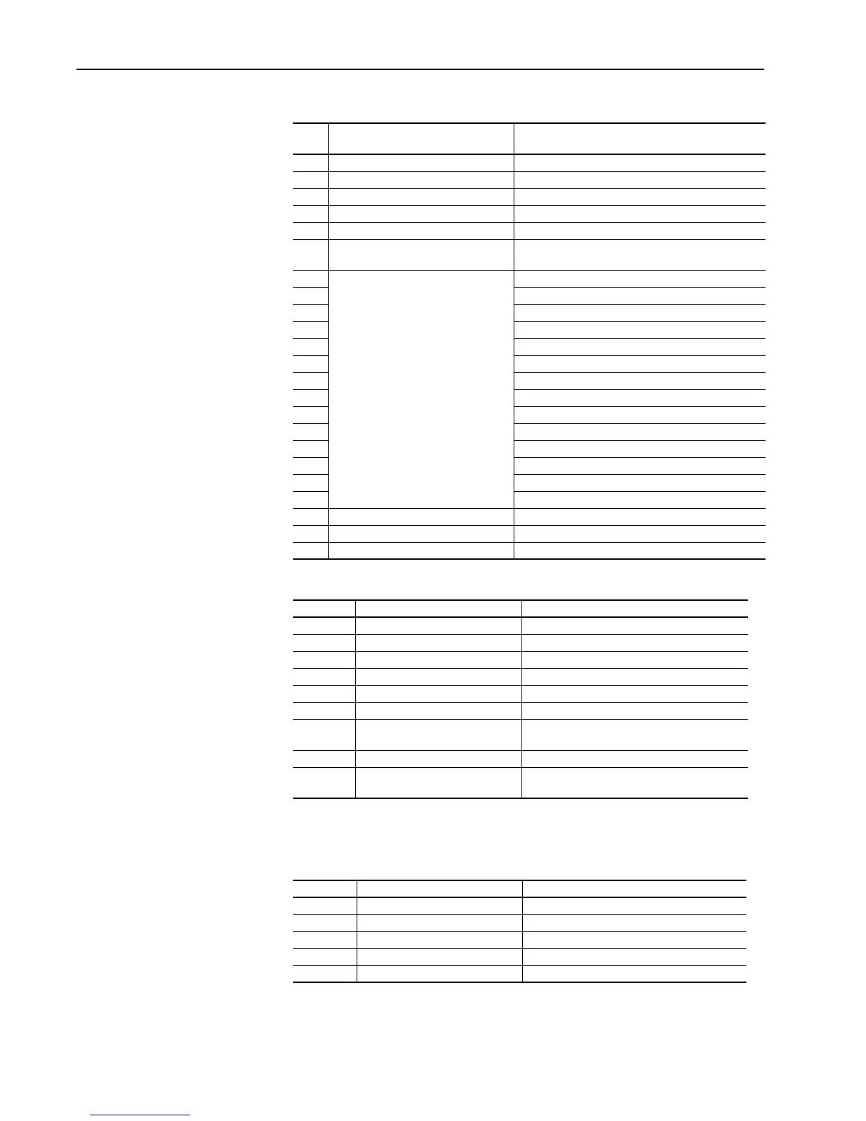
Table 6.C Series A Drives Rated 40-100 HP, 230V AC & 75-200 HP, 460V AC
Table 6.D Series B Drives Rated 125-300 HP, 230V AC & 250-600 HP, 460V AC
Power Supply Board
Table 6.E Series A Drives Rated 40-100 HP, 230V AC & 75-200 HP, 460V AC or
Series B Drives Rated 125-300 HP, 230V AC & 250-600 HP, 460V AC
Test
Point Normal Value Signal Description
1 12VDC (11.85/13.13) 12V DC Power Supply
2 +5V DC when field firing is enabled FFIREEN signal from Main Control Board
3 0V DC Not Used
4 +12, (+11.85/13.13)V DC +12V DC Power Supply
5 +24, ±6.0V DC +24V DC Power Supply
6 +5V DC when armature firing is
enabled
AFIREEN signal from Main Control Board
7
Test points TP7-TP20 are used to
monitor the gate pulses to the
armature and field SCRs. The
observed signal for these test points
will be a square wave, +24V to 0V DC,
120 degrees On & 240 degrees Off
when the particular SCR is being fired.
Bridge Armature; SCR 1F
8 Bridge Armature; SCR 5F
9 Bridge Armature; SCR 3F
10 Bridge Armature; SCR 4R
11 Bridge Armature; SCR 2R
12 Bridge Armature; SCR 6R
13 Field; FLD1
14 Armature; 2F
15 Field; FLD2
16 Armature; 4F
17 Armature; 5R
18 Armature; 6F
19 Armature; 1R
20 Armature; 3R
21 0V DC when Relay K3 is energized Control Signal to K3
22 +5, (±0.02V DC) +5V DC power supply
23 +0, +0V DC Control common (TE signal ground)
Test Point Normal Value Signal Description
1 12V DC (11.85 / 13.13) 12VDC Power Supply
2 0V DC when relay K3 is energized Control signal to K3
3 0V DC Control common (TE signal ground).
4 +5 á¿0.02V DC) +5V DC power supply
5 +12 (11.85 / 13.13)V DC +12V DC power supply
6 +24, á¿6.0)V DC +24V DC power supply
7 +5V DC when armature firing is
enabled.
AFIREEN signal from Main Control Board
8 Not Used Not Used
9 +5V DC when field firing is
enabled
FIREEN signal from Main Control Board
Test Point Normal Value Signal Description
1 +12V DC (11.85 / 13.13) +12V DC Power Supply
2 +5V DC á¿0.02V DC) +5V DC Power Supply
3 Internal use
4 12V DC (11.85 /13.13) 12V DC Power Supply
5 0V DC Control Common (TE Signal Ground)
Aotewell Ltd industry-mall.net
 Loading...


