Malfunctions Not Indicated by a Fault 3-13
Analog Tachometer
Malfunction
The analog tachometer device generates a DC voltage that is direction
sensitive and proportional to speed. The tach output must be connected to
an analog input channel on the Discrete Adapter Board. Most industrial
tachs have an output greater than the +/-10V range of the analog inputs. The
tach output must be scaled down, by an external voltage divider network.
The tach signal then must be scaled in the adapter card to determine the
proper relationship of output voltage/motor velocity to Base Speed in Drive
Units. This scaled configuration data must then be linked to Parameter 156
“Tach Velocity”
Many problems relate to the scaling of the tach signals. Below is a
procedure for checking the scaling of the analog tach feedback for proper
drive operation.
1. Determine the Volts/RPM rating of the tach. It is usually on the tach
nameplate. Multiply this rating times the absolute maximum speed the
motor will be commanded to accelerate to. (This value should also be
programmed in Parameter 607 “Rev Speed Lim” and 608 “Fwd Speed
Lim” to ensure the velocity command will be properly clamped).
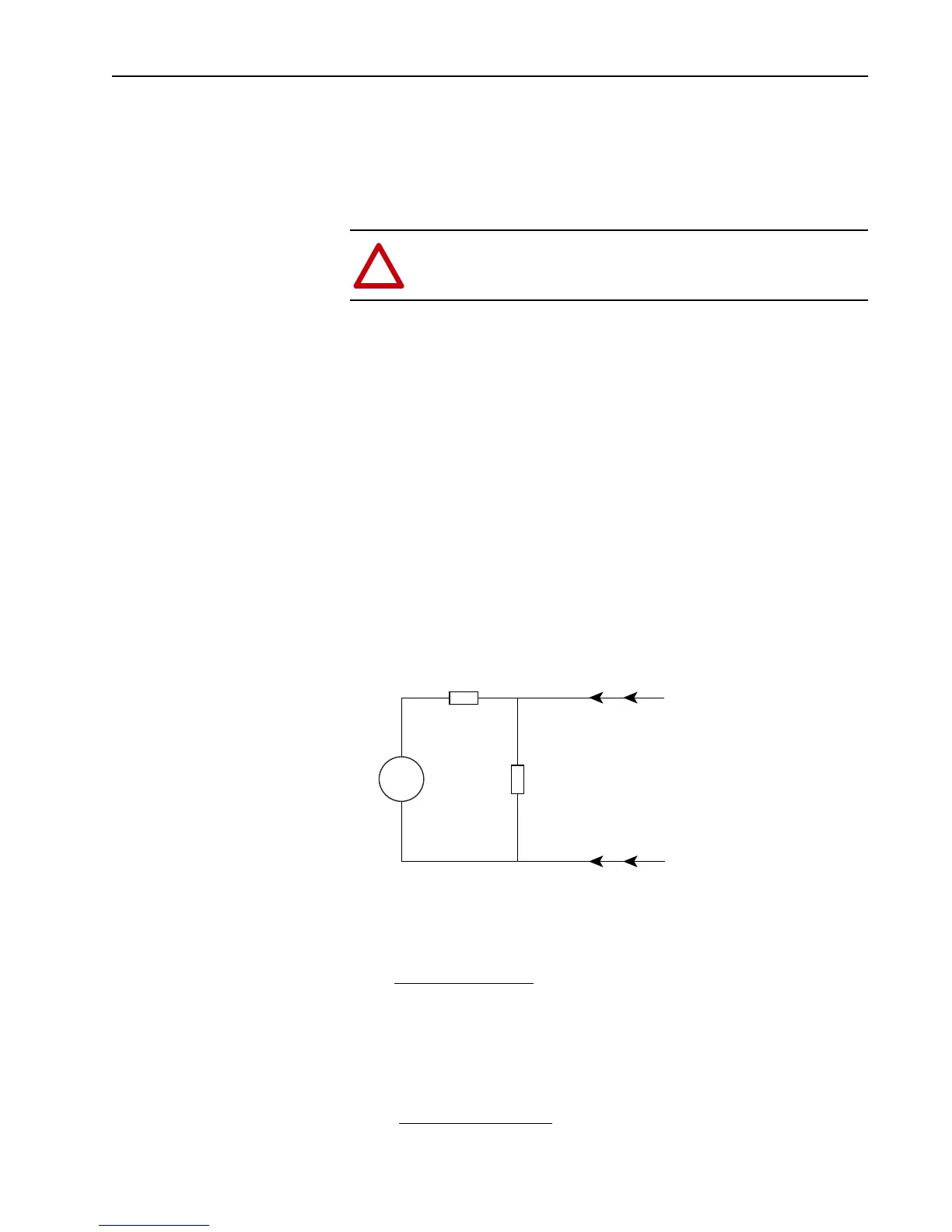
2. This Max Volts output must be scaled to a level within the +/- 10V
analog input channel range. This can be accomplished by using a voltage
divider that will take the Max Volts output and scale it to a maximum 9V
input. This allows for protection against 10% overshoot.
This circuit uses a 10k resistor across the input channel and R1
represents the dropping resistor for the scaling network. To determine
the value of R1 use the following equation:
3. The analog input channel on the adapter board must now be scaled to
represent an accurate velocity feedback signal. First determine the
analog input signal for base speed. Parameter numbers are given in ( )
where applicable
!
ATTENTION: Connecting a Tach which has an output range
greater than +/-10V directly to the analog input channel can
severely damage the adapter card.
Tach
R1
10k
+
–
TB3
TB3
Analog In +
Analog In –
Adapter Board
20k Input Impedance
(Max Volts Output) x 6666
9V
– 6666 = R1
Base Motor Speed (606) x 9V
Max Speed
= Base Speed Input
Aotewell Ltd industry-mall.net
 Loading...


