2-18 Malfunctions with Indications
VP-19 Contactor Failure
(Soft)
(Parameter 101
bit 9 when
Parameter
630=1)
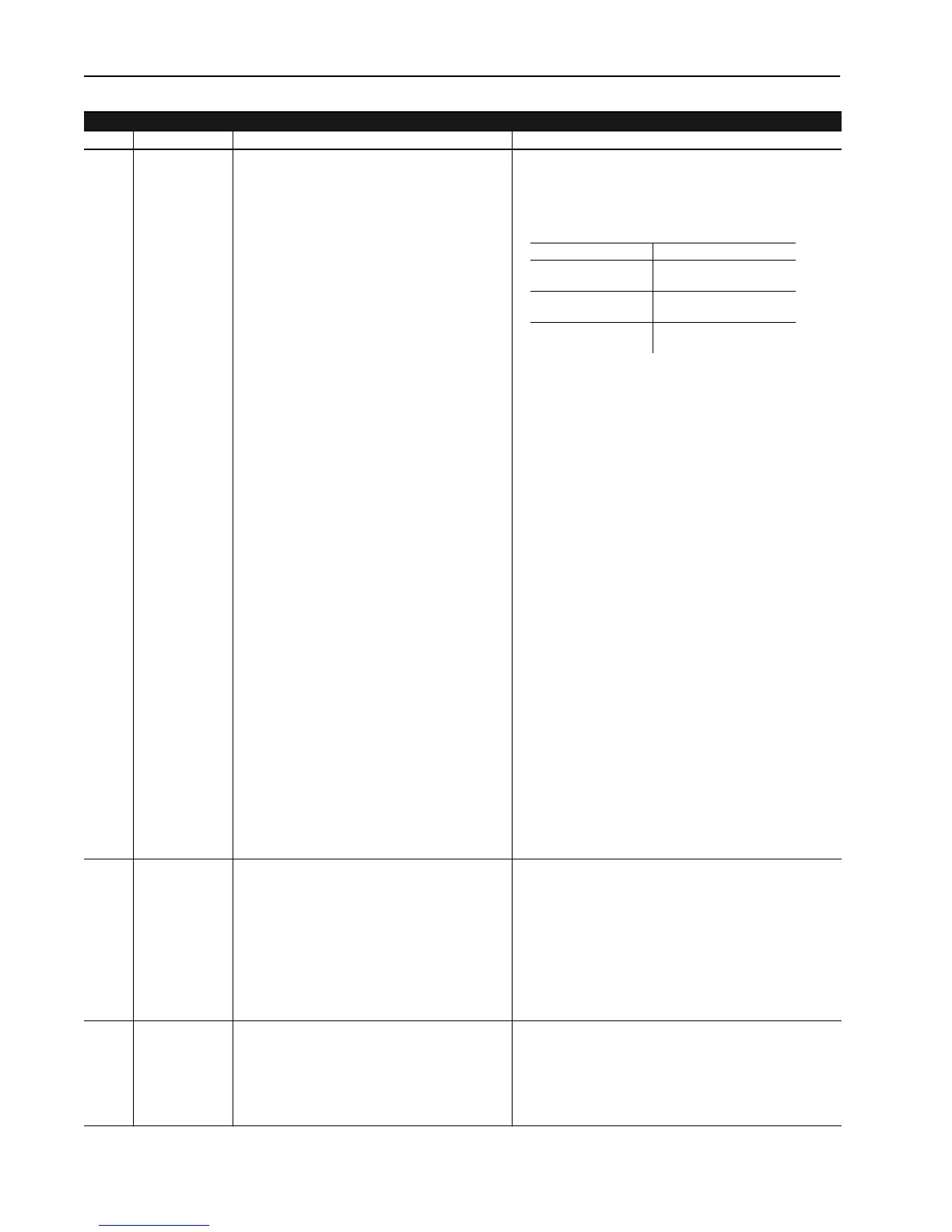
3. If external contacts exist between these terminals verify
them for proper operation. If an external control of the
contactor is not used, be sure a jumper is in place as
shown below.
4. An installation or wiring problem with the auxiliary contact
block (M1-X) mounted on the DC contactor. Verify that it is
properly installed and that the wiring is correctly installed
and tight. Vibration due to the opening and closing of the
contactor can loosen them so that connection contact is
lost.
5. A malfunction of the DC contactor (M1). With power
removed, verify that nothing is inhibiting the opening or
closing of the contactor. Apply power and verify that 115V
AC is applied across the coil of the contactor when it is
commanded to close. If it is present, but the contactor
does not close, then replace the DC Contactor.
6. A malfunction of the Pilot Relay (PR). If no voltage was
present across the contactor coil when commanded to
close then verify that 115V AC is present across J1p1 and
2 on the PSI Board for Series A Drives (SP1-1 and 2 for
Series B). If it is present, then check the wiring that goes
to the Pilot Relay. If all is in order then replace the Pilot
Relay.
7. A malfunction of the Power Stage Interface Board (PSI). If
no voltage was present across J1p1 and 2 on Series A
(SP1-1and 2 on Series B) when the contactor is
commanded to close and the fault still occurs, then
replace the PSI Board.
8. A malfunction on the Main Control Board. If after replacing
the PSI Board the “Contactor Malfunction” fault still occurs
then replace the Main Control Board.
VP-20 AC Voltage
(Selectable)
(Parameter 101
bit 10 when
Parameter
630=1)
This fault occurs when the incoming AC line
voltage deviates by more than +15% or -20% of the
level specified in parameter 617 “Rated AC Line”
for a time period greater than Param 728. This fault
is type selectable as either Soft or Warning. A Soft
Fault selection will cause a controlled stop to be
initiated.
1. Verify and correct the cause of the AC line voltage
variance. If no variances can be detected, measure the
RMS line voltage during worse case motor load
conditions. If the line voltage drops significantly under
load, the voltage source kVA output may be insufficient for
the application. Execute a Clear Fault to continue
operation.
2. Verify RMS Line to Line value read with DVM to value
reported by Param 116. Adjust Param 740 as required.
VP-21 Handshake With
SP (Hard)
(Parameter 101
bit 11 when
Parameter
630=1)
Internal communication between processors has
malfunctioned. A coast stop will be initiated.
Execute System RESET or cycle power and attempt normal
operation. If the fault reoccurs, replace Main Control Board.
Velocity Processor Faults
No. Name Description Recovery
HP 115VAC Input Connection
1-30 HP, 230V AC
2-60 HP, 460V AC
TB2 - 6 and 7
40 - 100 HP 230VAC 75 -
200 HP 460VAC
TB2 - 8 and 9
125-300 HP, 230V AC
250-600 HP, 460V AC
TB5 - 8 and 9
Aotewell Ltd industry-mall.net

 Loading...


