Malfunctions Not Indicated by a Fault 3-31
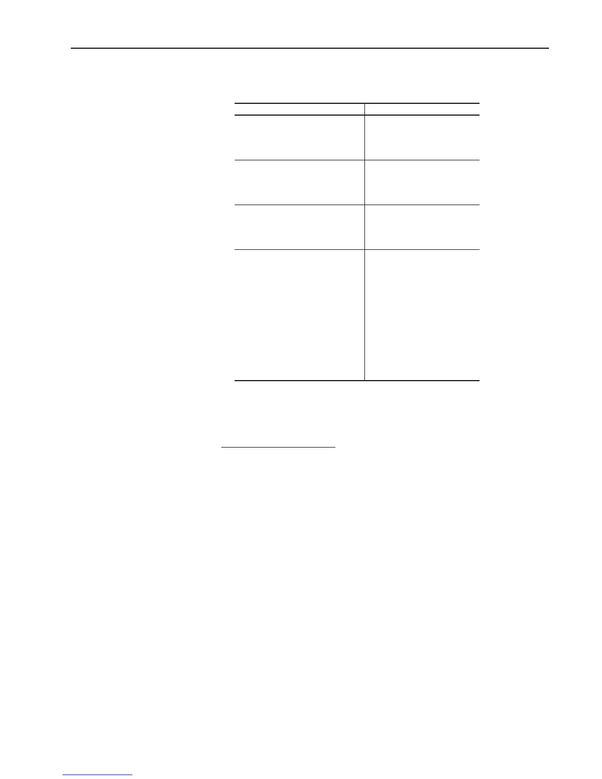
2. Remove the armature gate leads J15 thru J26. Measure the following
resistances with a DMM on the 200 ohm scale.
If any of these measurements are out of tolerance, replace the power
board.
Field SCR Module (Series B)
The 1395 Series B field supply consists of a single quad pack SCR module
arranged as a single phase full wave rectifier. Malfunction of this
component may cause various reponses including field and velocity related
faults, or blown F1 and F2 fuses. The following procedure can be used if
field bridge malfunctions are suspected.
1. Disconnect and lock out all incoming voltage sources. Verify the 3 phase
high voltage is removed from the input fuses F1 - F3. Also verify the
115V logic and contactor power are removed from TB2 of the PSI/
Switcher board.
2. To gain access to the power board, swing down and remove the PSI/
Switcher board.
3. Remove all interconnects to the field bridge.
Measurement Point Measurement
J15 to A1 (bottom side of contactor)
J16 to L1
J17 to A2 (bottom side of contactor)
J18 to L1
100 ohms +/–10%
J19 to A1 (bottom side of contactor)
J20 to L2
J21 to A2 (bottom side of contactor)
J22 to L2
100 ohms +/–10%
J23 to A1 (bottom side of contactor)
J24 to L3
J25 to A2 (bottom side of contactor)
J26 to L3
100 ohms +/–10%
J6-6 to J6-1
J6-8 to J6-1
J6-9 to J6-1
J6-10 to J6-1
J6-11 to J6-1
J6-12 to J6-1
J6-13 to J6-1
J6-14 to J6-1
J6-15 to J6-1
J6-16 to J6-1
J6-18 to J6-1
J6-20 to J6-1
100 ohms +/–10%
Aotewell Ltd industry-mall.net

 Loading...


