Publication 1398-5.1 — January 2000
2-10 Install the ULTRA Plus PDM Components
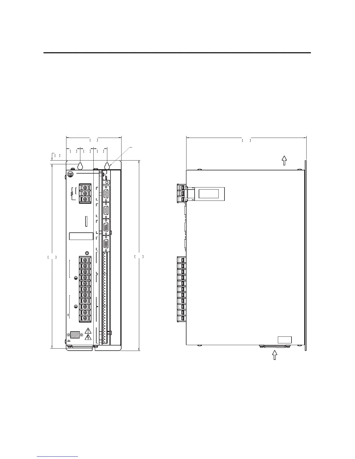
Mounting Requirements
3RVLWLRQWKH8/75$3OXV3'0LQDYHUWLFDOSRVLWLRQRQDIODWVROLGVXUIDFH
WKDWPHHWVWKHPRXQWLQJUHTXLUHPHQWVIRUZHLJKWKXPLGLW\DQGWHPSHUDWXUH
OLVWHGLQ$SSHQGL[$7KHIROORZLQJGLDJUDPVOLVWGLPHQVLRQDOPRXQWLQJ
UHTXLUHPHQWV
Figure 2.5
1398-PDM-10, 20 and 30 Mounting
P1
14.20
360.6
13.75
349.2
1.00
25.4
1.05
26.6
1.00
25.4
4.10
104.1
0.27
7.0
CLEARANCE HOLES FOR #10
(M5) MOUNTING SCREWS
8.93
226.8
SW1
U10
EXHAUST
AIR
AIR INTAKE
Digital Inputs
TB1
1
1
10
5
L1 Aux
L2/N Aux
L1
L2/N
DC Bus+
DC Bus-
100-240 Vac 50/60 Hz
5
Digital
And
Inputs
P2
10
Outputs
I/O
Analog
P3
5
Status/
1
P4
Encoder 2
Auxiliary
P5
Encoder 1
Motor
T
R
S
Motor
DC Bus
After Removing Power
May Exist Up To Five Minutes
High VoltageWARNING:
P6
Serial 2
Computer
P7
Auxiliary
Serial 1
Status
Ultra Plus Series
Allen-Bradley
TB2
1
3
2
Internal
External Shunt

 Loading...


