40752-165(1)Effective March 2008
Trip Device Adjustment for MCPs
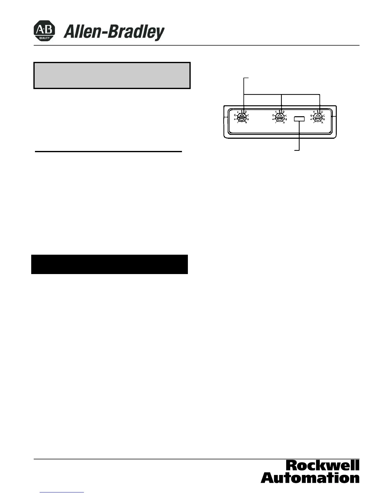
The magnetic element of each pole of the trip device
can be adjusted by rotating the adjustment buttons (Fig.
3-2) on the front face of the trip unit with a screwdriver.
The buttons have nine settings, which are indicated on
the nameplate with letters A through l; The ampere set-
tings are shown on the MCP nameplate and in Table 3-
1. To adjust the setting, rotate each button clockwise
until arrow on button points to desired setting.
Conforming to NEC requirements, the maximum MCP
trip ampere value is set by the motor FLA. Since there
are various types and classes of motor designs (based
on duty cycle, electrical load, and manufacturer's discre-
tion) locked rotor currents(and therefore inrush current
magnitudes)vary.These are normally identified by NEC
codes. The Listed MCP trip ampere value is considered
typical but not all inclusive. This is the reason for the
adjustable magnetic trip setting; that is, to compensate
for different actual motor Inrush currents. That adjust-
ments need be made, is not only normal, but sometimes
necessary to enable the motor to start without nuisance
trip ping, particularly when motor or system conditions
induce higher than expected inrush currents. These cir-
cumstances could be beyond the control of the MCP so
far as its allowable trip setting is concerned and should
be treated as a special case, referable to Allen-Bradley.
Table 3-1 MCP Trip Settings (Cont.)
Cam Motor NEMA Continuous MCP MCP
Setting Full Load Starter Amps Catalog Trip
Current Size Number Setting
Amperes
A 96.2 – 108.0 5 1250
B 108.1 – 119.9 5 1405
C 120.0 – 132.3 5 1560
D 132.4 – 144.2 5 1720
E 144.3 – 156.1 5 250
140M-JD8P-D20 1875
F 156.2 – 168.0 5 2030
G 168.1 – 179.9 5 2185
H 180.0 – 192.3 5 2340
I 192.4 – 204.0 5 2500
MCP Reset
After an automatic or accessory initiated trip, or a manu-
al Push-to-Trip operation, the MCP is reset by moving
the MCP handle to the extreme OFF position.
No MCP should be reclosed until the cause of trip is
known and the situation rectified.
PUSH-TO-TRIP Button
The PUSH-TO-TRIP button checks the MCP tripping
function and is used to periodically exercise the operat-
ing mechanism. The button is designed to be operated
by a small screwdriver.
NOTICE
Figure 3-2 Trip Device Adjustment Buttons
Trip Device
Adjustment Buttons
Push to Trip Button
See above For Trip Setting Values
To Set: Rotate Dials
Page 5
 Loading...