Compact 32-point 24V dc Sink/Source Input Module 7
Publication 1769-IN032A-EN-P - April 2003
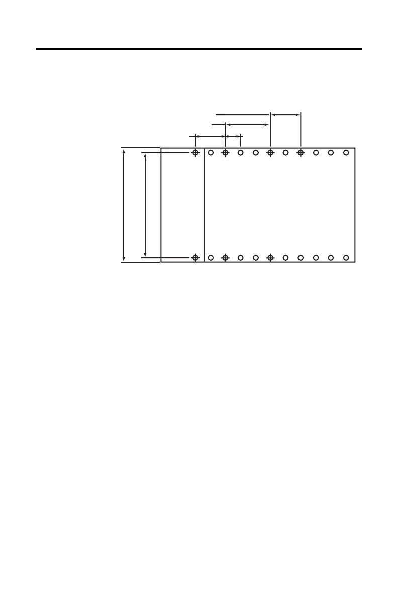
Panel Mounting Using the Dimensional Template
Locate holes every 17.5 mm (0.689 in.) to allow for a mix of single-wide and
one-and-a-half-wide modules (e.g., 1769-OA16).
Panel Mounting Procedure Using Modules as a Template
This procedure lets you use the assembled modules as a template for drilling holes
in the panel. If you have sophisticated panel mounting equipment, you can use the
dimensional template provided on
page 7. Due to module mounting hole tolerance,
it is important to follow these procedures:
1. On a clean work surface, assemble no more than three modules.
2. Using the assembled modules as a template, carefully mark the center of all
module-mounting holes on the panel.
3. Return the assembled modules to the clean work surface, including any
previously mounted modules.
4. Drill and tap the mounting holes for the recommended M4 or #8 screw.
5. Place the modules back on the panel, and check for proper hole alignment.
6. Attach the modules to the panel using the mounting screws.
Spacing for single-wide modules 35mm (1.378 in.)
Spacing for one-and-a half-wide modules 52.5mm (2.067 in.)
Refer to host controller documentation for this dimension.
Host Controller
Note: Overall hole spacing
tolerance: ±0.4mm (0.016 in.).
30535-M

 Loading...


