4
Publication 1794-IN102B-EN-P - June 2004
Wiring Connections for the 1794-IA8I
1794-TB2, -TB3, or -TB3S Terminal Base Wiring for the
1794-IA8I
1794-TBN Terminal Base Wiring for 1794-IA8I
Configuring Your ac Input Module
Image Table Memory Map for the 1794-IA8, -IA8K
and -IA8I
.
Image Table Memory Map for the 1794-IA16
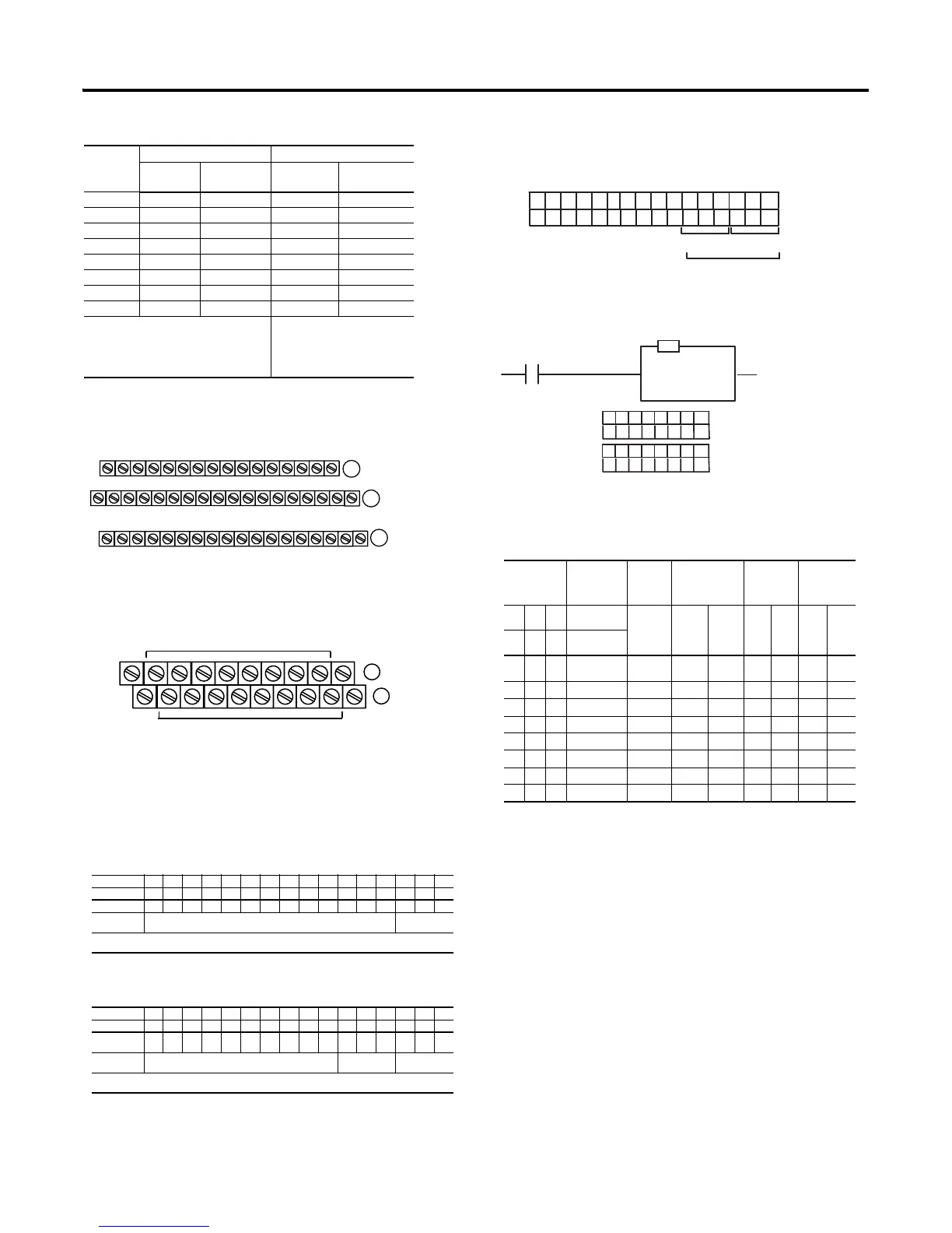
Setting the Input Filter Time
You can increase the input filter time (FT) for channels 00-07 (1794-IA8,
-IA8K, -IA8I) and channels 00-15 (1794-IA16) by setting the corresponding
bits in the output image table (complementary word) for the module.
For example, to increase the off-to-on filter time to 12ms for all inputs at
address rack 1, module group 0, set bits and program as shown below.
To increase the filter time, set the bits according to the table below.
Input Filter Time
Input
1794-TB2, -TB3, -TB3S 1794-TBN
Input
Terminal
120V ac L2
Common
Input
Terminal
120V ac L2
Common
Input 0 A-0 A-1 B-0 C-1
Input 1 A-2 A-3 B-2 C-3
Input 2 A-4 A-5 B-4 C-5
Input 3 A-6 A-7 B-6 C-7
Input 4 A-8 A-9 B-8 C-9
Input 5 A-10 A-11 B-10 C-11
Input 6 A-12 A-13 B-12 C-13
Input 7 A-14 A-15 B-14 C-15
A = Even numbered terminals 0 thru 14 for customer
connections; corresponding odd numbered 120V ac
common L2 terminals 1 thru 15 for customer
connections from isolated power supply.
B = Even numbered terminals 0 thru 14
for customer connections; C = Odd
numbered120V ac common L2
terminals 1 thru 15 for customer
connections from isolated power
supply.
Dec. 15 14 13 12 11 10 9 8 7 6 5 4 3 2 1 0
Oct. 17 16 15 14 13 12 11 10 7 6 5 4 3 2 1 0
Read I7 I6 I5 I4 I3 I2 I1 I0
Write Not used - set to 0 Filter Time FT
0-7
Where I = Input
FT = Input filter time.
Dec. 15 14 13 12 11 10 9 8 7 6 5 4 3 2 1 0
Oct. 17 16 15 14 13 12 11 10 7 6 5 4 3 2 1 0
Read 1 I
15
I
14
I
13
I
12
I
11
I
10
I9 I8 I7 I6 I5 I4 I3 I2 I1 I0
Write 3 Not used - set to 0 Input Filter FT
12-15
Input Filter FT
0-11
Where I = Input
FT = Input filter time
17 18 19 20 21 22 23 24 25 26 27 28 29 30 31 32 33
0 1 2 3 4 5 6 7 8 9 10 11 12 13 14 15
16
35 36 37 38 39 40 41 42 43 44 45 46 47 48 49 50 51
34
(1794-TB3 show
A
B
C
onnect Inputs to even numbered terminals on row (A)
onnect 120V ac common L2 to odd numbered terminals on row (A)
16
0
1
2
3
4
5
6
7
8
9
10
11
12
13
14
15
51
33
34
B
C
Even Numbered I/O Terminals 0 thru 14
Odd Numbered I/O Terminals 1 thru 15
(1794-TBN show
onnect Inputs to even numbered terminals on row (B)
2 = 120V ac common - Connect to odd numbered terminals on row (C
Bits Description
Maximum
Filter Time
1794-IA8, -IA8K
(ms)
Maximum
Filter Time
1794-IA8I
(ms)
Maximum
Filter Time
1794-IA16
(ms)
02 01 00 Filter Time -
inputs 00-11
Selected
Filter
Time
Off to
On
On to
Off
Off
to
On
On
to
Off
Off
to
On
On
to
Off
05 04 03 Filter Time -
inputs 12-15
0 0 0 Filter Time 0
(Default)
256µs 8.4 26.4 8.4 26.4 7.5 26.5
0 0 1 Filter Time 1 512µs 8.6 26.6 8.6 26.6 8 27
0 1 0 Filter Time 2 1ms 9 27 9 27 9 28
0 1 1 Filter Time 3 2ms 10 28 10 28 10 29
1 0 0 Filter Time 4 4ms 12 30 12 30 12 31
1 0 1 Filter Time 5 8ms 16 34 16 34 16 35
1 1 0 Filter Time 6 16ms 24 42 24 42 24.5 44
1 1 1 Filter Time 7 32ms 40 58 40 58 42 60.5
15 14 13 12 11 10 9 8 7 6 5 4 3 2 1 0
FT = 12-15 FT = 0-11
1794-IA8, -IA8I
1794-IA16
O:010
Dec.
1
00
76543
FLL
I:000
00
Fill File
Source
Destination
Length
#O:010
1
Write FT to complement
of input module.
Write filter time on system startup.
765432 1 0
0
1
0
= 4 Octal or 4 Decimal
21 0
= 44 Octal or 36 Decimal
010100
1794-IA8
1794-IA16
1794-IA8I

 Loading...


