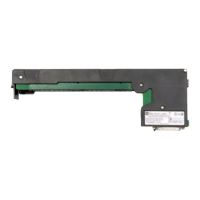
Do you have a question about the Allen-Bradley 1794-IRT8 and is the answer not in the manual?
| Manufacturer | Allen-Bradley |
|---|---|
| Product Type | FLEX I/O RTD Input Module |
| Input Type | RTD |
| Number of Inputs | 8 |
| Communication Interface | FLEX I/O |
| Resolution | 16 bits |
| Isolation | 1500 V AC |
| Operating Temperature | -40 to 70 °C (-40 to 158 °F) |
| Storage Temperature | -40 to 85 °C (-40 to 185 °F) |
| Relative Humidity | 5 to 95% (non-condensing) |
| Isolation Voltage | 1500 V AC |
| RTD Types | Pt100, Pt1000, Ni100, Ni120 |
| Resistance Range | 0…400 Ω |
| Certifications | CE |
| Voltage Category | Not Applicable |
Describes the function and capabilities of the 1794-IRT8 Thermocouple/RTD/mV Input Module.
Explains how TC/RTD/mV modules communicate with programmable controllers using block transfer.
Illustrates the communication flow between an adapter and the module.
Details the physical features and status indicators on the 1794-IRT8 module.
Covers pre-installation checks, EU directives (EMC, Low Voltage), and important notes.
Details power requirements, current draw limitations, and wiring considerations.
Explains daisy-chaining and individual wiring methods for terminal base units.
Provides instructions for mounting the terminal base unit on a DIN rail or panel.
Details the procedure for installing the 1794-IRT8 module onto its terminal base unit.
Describes the function and meaning of the module's Power (PWR) and Fault (F) indicators.
Explains the need for block transfer instructions for module configuration and data transfer.
Covers block transfer programming specifics for different Allen-Bradley PLC families.
Provides example ladder logic for block transfer read/write with PLC-5/250 processors.
Describes how to configure module features using data table words and block transfer.
Lists supported RTD and Thermocouple sensor types and their selectable ranges.
Explains how input/output data is mapped into the module's image table.
Provides bit/word descriptions for block transfer read and write operations.
Covers DeviceNetManager software, I/O structure, and polled I/O.
Details the structure and bits of the adapter's input status word.
Explains system throughput factors and data mapping in the image table.
Describes factory default values for module configuration and I/O data.
Introduces module calibration, when to perform it, and available methods.
Lists required tools, calibration setups, and wiring connections for calibration.
Provides step-by-step instructions for manually calibrating module offsets and gains.
Details read/write words and EDT commands used for module calibration.
Explains the procedures for calibrating current sources and cold junction compensation.
Presents detailed technical specifications for the 1794-IRT8 Thermocouple/RTD/mV Input Module.
Outlines available technical support services, including SupportPlus and telephone support.
Describes engineering assistance, technical training, and repair/exchange services.


