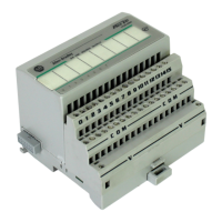
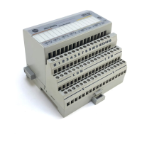
18 FLEX I/O AC Digital Output Modules
Publication 1794-IN103D-EN-P - July 2018
(2)
Output signal delay is the time from receipt of an output on or off command to the output actually turning on or off.
(3)
Module outputs are not fused. Fusing is recommended. If fusing is desired, you must supply external fusing or use the
1794-TBNF terminal base, if recommended.
(4)
Auxiliary terminal strips are required when using the 1794-TBN.
Specifications – 1794-OA16
Attribute Value
Number of outputs 16, nonisolated
Recommended terminal base unit 1794-TBN
(5)
, 1794-TBNF, 1794-TB2, 1794-TB3, 1794-TB3S,
1794-TBKD, 1794-TBNK, 1794-TBNFK, 1794-TB3K, 1794-TB3SK
Mounting See derating curve
Output voltage range, min 74V AC
Output voltage range, nom 120V AC
Output voltage range, max 132V AC
Output current rating
(1)
4.0 A (16 outputs @ 250 mA)
On-state current, min 5.0 mA per output
On-state current, max
(2)
500 mA per output @ 55 °C
On-state voltage drop, max 1.5V @ 0.5 A
Surge current 7 A for 40 ms, repeatable every 8 seconds
Off-state leakage current, max 2.25 mA
Isolation voltage 120V (continuous), field to backplane
Tested @ 1250V AC for 60 s
No isolation between individual channels.
Output signal delay
(3)
Off to On
On to Off
1/2 cycle max
1/2 cycle max
FlexBus current 80 mA @ 5V DC
Power dissipation, max 4.7 W @ 0.5 A
Thermal dissipation, max 16.1 BTU/hr @ 0.5 A
Fusing
(4)
2.5 A, 150V AC normal blow, MQ2
(1)
If using 0.5 A outputs, alternate wiring so that no two 0.5 A outputs are next to each other.
(2)
Below 50 mA the voltage drop across the module will be higher and the voltage waveform may have some small
oscillation (less than 5V).
(3)
Output signal delay is the time from receipt of an output on or off command to the output actually turning on or off.

 Loading...


