Do you have a question about the Allen-Bradley 1756 Series and is the answer not in the manual?
Provides an overview of updates and new information in the publication.
Defines key terms and abbreviations used throughout the manual for clarity and understanding.
Lists related Rockwell Automation publications and resources for further information.
Introduces the 1756 ControlLogix digital safety I/O modules and their basic functionality.
Details the compatibility requirements between controllers, software, and the safety I/O modules.
Explains the safety ratings and certifications applicable to the modules for safety applications.
Outlines the process and considerations for ensuring system conformity with safety standards.
Describes the single-channel operation mode specific to the 1756-IB16S input module.
Details the single-channel and dual-channel operation types for the 1756-OBV8S output module.
Provides instructions on how to acquire and verify the firmware for the safety I/O modules.
Lists critical safety precautions to be followed when using the safety I/O modules.
Outlines the necessary evaluations and requirements for safety application design.
Defines the safe state of the safety modules and its implications for system operation.
Explains the concepts of configuration signature and ownership for safety modules.
Guides on how to reset modules to their default factory configuration.
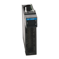
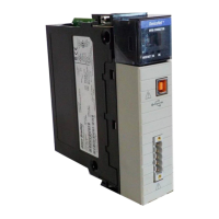
Provides a general description and visual identification of the safety I/O modules.
Differentiates between local and remote I/O module configurations.
Explains the controller ownership concept for I/O modules in a system.
Provides steps and requirements for building a system with safety I/O modules.
Details the process of configuring the safety I/O modules using Logix Designer.
Explains how connections are established between controllers and safety I/O modules.
Describes configuration options that determine data exchange between controller and module.
Details the available data type choices for configuring safety I/O modules.
Explains the RPI parameter and its role in data exchange between controller and module.
Describes how remote safety modules connect and transmit data over an EtherNet/IP network.
Explains how safety input modules operate and exchange data with controllers.
Explains how safety output modules operate and exchange data with controllers.
Outlines restrictions on operations that can disrupt module operation.
Details the types of sensing devices compatible with safety input modules.
Details the types of output devices compatible with safety output modules.
Explains how modules are configured and monitored using Logix Designer software.
Describes how data quality is reported and indicated for safety I/O modules.
Explains how fault and status data is reported through Logix Designer and indicators.
Describes how to temporarily suspend module connections without removal.
Explains electronic keying to prevent using incorrect devices and its attributes.
Discusses how to obtain and update module firmware revisions.
Explains the Producer/Consumer communication model used by safety I/O modules.
Introduces features specific to the 1756-IB16S safety input module.
Details the safety application suitability levels for the 1756-IB16S module based on standards.
Explains how test outputs can be used with safety inputs for fault detection.
Describes the single-channel operation for the 1756-IB16S module and its effect on suitability.
Details the user-configurable fault reset modes for safety input channels.
Explains how to increase transition times for input signals to improve noise immunity.
Explains the module status indicator for module health.
Details how input modules report fault and status data via module tags.
Describes the feature that monitors for loss of field-side power and its fault detection.
Explains how short circuit protection prevents damage to test outputs.
Introduces features specific to the 1756-OBV8S safety output module.
Details the safety application suitability levels for the 1756-OBV8S module based on standards.
Explains how safety outputs can be pulse-tested for continuous channel ability testing.
Describes the single-channel operation for the 1756-OBV8S module and its effect on suitability.
Describes the dual-channel operation for the 1756-OBV8S module and its connection pairs.
Details the user-configurable fault reset modes for safety output channels.
Explains how output modules report fault and status data via module tags.
Explains the module status indicator for module health.
Describes how to check individual output points for faults like short circuits.
Describes the feature that monitors for loss of field-side power and its fault detection.
Explains the feature that detects disconnected wires or missing loads for output points.
Explains how short circuit protection prevents damage to output terminals.
Lists conditions that can trigger the short circuit diagnostic on the output module.
Details test output recovery after overload or short circuit to ground conditions.
Explains how thermal shutoff prevents output damage from excessive heat.
Describes how to configure output states for program and fault modes.
Explains how to configure module behavior when a connection fault occurs.
Describes how to use forces to override data for testing and debugging.
Guides on creating new local or remote safety I/O modules in a project.
Explains how to edit common configuration categories for safety I/O modules.
Details how to configure categories specific to the 1756-IB16S input module.
Details how to configure points for the 1756-OBV8S output module.
Guides on how to view module tags in the Logix Designer Tag Editor.
Provides instructions and considerations for replacing safety modules in a system.
Describes the meaning of the status indicators on the safety I/O modules.
Details the status of the module's OK indicator and troubleshooting guidance.
Explains the I/O Status (ST) and Fault Status (FLT) indicators for troubleshooting.
Describes how to find fault information within module properties categories.
Shows where module status is indicated on the General category of Module Properties.
Explains how fault descriptions and error codes appear on the Connection category.
Explains where major and minor fault information is listed in the Module Info category.
Explains how to use diagnostics to monitor module and point conditions.
Describes how module diagnostics provide module-wide operating information.
Details how to check individual points for faults like short circuits.
Shows how fault conditions are indicated within the controller tags in the Tag Editor.
Describes conditions that can trigger an InternalFault on safety output modules.
Guides on how to access module tags through the Logix Designer Tag Editor.
Explains the naming conventions used for module tags.
Lists and describes the input and output tags specific to the 1756-IB16S module.
Lists and describes the input and output tags specific to the 1756-OBV8S module.
Provides example wiring diagrams for the 1756-IB16S safety input module.
Provides example wiring diagrams for the 1756-OBV8S safety output module.
Lists calculated safety data parameters, including PFD and PFH, for the 1756-IB16S module.
Lists calculated safety data parameters, including PFD and PFH, for the 1756-OBV8S module.
| Series | 1756 |
|---|---|
| Brand | Allen-Bradley |
| Category | Control Unit |
| Product Type | Programmable Logic Controller (PLC) |
| Communication Options | EtherNet/IP, ControlNet, DeviceNet |
| I/O Modules | Digital, Analog, Specialty |
| Programming Software | Studio 5000 |
| Memory | Varies by processor |
| Operating Temperature | 0 to 60°C (32 to 140°F) |
| Certifications | UL, CE, ATEX |
| Processor Options | ControlLogix, CompactLogix |


