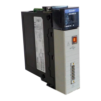
Do you have a question about the Allen-Bradley 1756-DHRIO and is the answer not in the manual?
Explains the communication types supported: DH+ messaging, CIP messaging, and Remote I/O.
Details the module's ability to route messages through up to four networks and three chassis.
Explains the module's function as a scanner in a remote I/O network, transferring data.
Highlights key features like routing tables, communication capabilities, and hot-swapping.
Details how to set network type and node address switches for DH+ or RIO configurations.
Provides guidelines to prevent ESD damage to the module during handling.
Explains precautions for installing or removing the module while chassis power is applied.
Defines Data Highway Plus as a wire/protocol connecting devices, supporting up to 32 stations per link.
Provides design practices, performance requirements, and cable considerations for DH+ links.
Lists various devices and their required catalog numbers and cables for connecting to a DH+ link.
Offers guidelines for configuring DH+ links, such as minimizing nodes and limiting stations for response times.
Describes local DH+ messaging for communication between devices on the same physical link.
Describes remote DH+ messaging for communication between devices on physically separate networks.
Describes routing tables used to steer remote DH+ messages and how to configure them using RSLinx.
Presents an example of a DH+ routing configuration, illustrating node and link ID assignments.
Describes CIP messaging as a mechanism on ControlLogix, ControlNet, and Ethernet, using a relative path.
Provides a table matching software requirements (RSLinx, RSLogix) to product types (PLCs, SLCs, ControlLogix).
Explains how RSLinx is used to create routing tables for DH+ networks, defining link IDs and paths.
Explains ControlLogix routing using CIP and relative paths, simplifying maintenance and offering alternative paths.
Explains how to set the controller slot, the physical location of a ControlLogix controller, for DH+ applications.
Details steps for using RSLogix 5 to send read/write message instructions from PLC-5s in DH+ applications.
Details steps for using RSLogix 5000 to send read/write message instructions from ControlLogix controllers in DH+ applications.
Explains how to configure connection paths for controller-to-controller or workstation-to-controller communication.
Describes sending DH+ messages from a PLC-5 to another PLC-5 via a 1756-DHRIO module.
Describes sending DH+ messages from an SLC-504 through two 1756-DHRIOs to another SLC-504.
Describes sending DH+ messages from a PLC-5 through 1756-DHRIOs in separate chassis to another PLC-5.
Describes sending DH+ messages from a PLC-5 through 1756-DHRIO and 1756-CNB to a PLC-5C on ControlNet.
Describes sending DH+ messages from a PLC-5 to a ControlLogix controller using local DH+ messaging.
Describes sending DH+ messages from a PLC-5 to multiple ControlLogix controllers using local and remote DH+ messaging.
Describes sending DH+ messages from an SLC-504 through a 1756-DHRIO to another 1756-DHRIO and ControlLogix controller.
Describes sending DH+ messages from a ControlLogix controller to a PLC-5 using local DH+ messaging.
Describes sending DH+ messages from a ControlLogix controller to an SLC-5/04 over ControlNet and DH+ using remote DH+ messaging.
Describes sending CIP messages between ControlLogix controllers through a 1756-DHRIO module over one link.
Describes sending CIP messages between ControlLogix controllers over two links using 1756-DHRIO modules.
Explains the remote I/O system and the module's role as a scanner for I/O devices not in the controller's chassis.
Lists devices usable as adapters in a remote I/O network, including processors and operator interfaces.
Specifies rules for remote I/O networks: same communication rate, unique rack assignments, and device limits.
Explains how the module functions as a remote I/O scanner, transferring data between controllers and remote I/O devices.
Describes setting the Requested Packet Interval (RPI) for data exchanges between the module and controller.
Explains how communication interruptions trigger fault notifications and controller actions.
Details steps for using RSLogix 5000 with the 1756-DHRIO module in remote I/O applications.
Provides step-by-step instructions for adding the 1756-DHRIO module to a project in RSLogix 5000.
Explains how to configure the 1756-DHRIO module using wizard screens and lists configurable parameters.
Provides steps for adding a remote I/O adapter to the project in RSLogix 5000.
Details how to create message instructions for block transfers to move data between controllers and remote modules.
Describes scanning FLEX adapters through a single 1756-DHRIO module in the local chassis.
Describes scanning FLEX adapters through multiple 1756-DHRIO modules in the local chassis.
Describes scanning 1771 Remote I/O adapters through a 1756-DHRIO in a remote chassis over ControlNet.
Explains message timeouts and fault notifications associated with BT messages.
Describes DH+ ‘Pass-Through’ messages used for remote I/O block transfers and their destination addressing.
Describes initiating block transfers to remote FLEX I/O modules through a 1756-DHRIO in a local chassis.
Describes how to check power supply and module status indicators during power-up.
Explains the alphanumeric codes displayed by the module for diagnostic information.
Explains the meaning of LED status indicators for the module and each channel.
Specifies the module location as ControlLogix chassis.
Lists the available baud rates for the module.
Details environmental operating and storage conditions, including temperature, humidity, vibration, and shock.
Describes the Echo command and its reply, used for testing communication.
Explains the command to check the location and status of controlling devices on the DHRIO network.
Explains how to read diagnostic counters stored in the module's RAM for debugging and analysis.
Defines connections and discusses cached vs. uncached connections for DH+ and remote I/O.
Highlights controller limitations, including unconnected buffers (UCB) and I/O memory penalties.
Explains RPI settings for status information, discrete data from adapter racks, and block transfer updates.
Explains how to increase the UCB limit in RSLogix 5000 and the associated I/O memory penalty.
| Model | 1756-DHRIO |
|---|---|
| Category | Control Unit |
| Catalog Number | 1756-DHRIO |
| Number of Ports | 2 |
| Shock | 30 g |
| Vibration | 5 g |
| Product Type | Communication Module |
| Communication Protocols | Data Highway Plus, Remote I/O |
| Port Type | DH+ and RIO |
| Data Highway Plus Baud Rates | 57.6 kbps, 115.2 kbps |
| Baud Rate | 57.6 kbps, 115.2 kbps, 230.4 kbps |
| Operating Temperature | 0 to 60 °C (32 to 140 °F) |
| Storage Temperature | -40 to 85 °C (-40 to 185 °F) |
| Relative Humidity | 5 to 95% (non-condensing) |
| Module Location | Any slot in a 1756 chassis |
| Isolation Voltage | 50 V continuous |
| Certifications | CE, C-Tick, UL |


