Publication 1756-IN566B-EN-P - April 2001
Installation Instructions
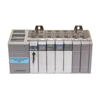
ControlLogix DeviceNet
Scanner Module
Catalog Number 1756-DNB
Use this manual as a guide to install the ControlLogix™ DeviceNet™
Scanner Module. The following table identifies what this manual
contains and where to find specific information.
Topic See Page
European Communities (EC) Directive Compliance 3
Preventing Electrostatic Discharge 4
Understand the Module’s Software Features 5
Identify Module Components 6
Prepare to Install the Module 7
Installing or Removing the Module Under Power 8
Determine Module Slot Location 9
Install the Module 10
Remove or Replace the Module 11
Wire the DeviceNet Connector 12
Connect the Module to the DeviceNet Network 13
Apply Chassis Power 13
Using the Manual Configuration Pushbutton 14
Interpreting the Alphanumeric Display 16
Interpreting the LED Status Indicators 19
ControlLogix Controller Interface 21
Hazardous Location Information 25
Specifications 27
Allen-Bradley