22 ControlLogix DeviceNet Scanner Module
Publication 1756-IN566B-EN-P - April 2001
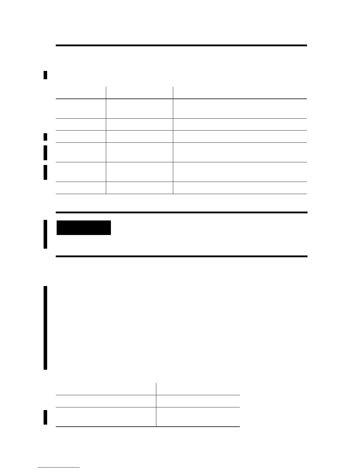
Module Command Register Bit Definitions
The bits of the Module Command Register are defined as follows:
Input Structure
The controller receives input I/O by reading input data from an input
structure in the 1756-DNB module. The scanner module receives
input data from DeviceNet modules and delivers a copy of these
values to the controller. The input structure consists of one 32-bit
status register and a variable size 32-bit array of up to 124 words for
input data. The 32-bit status register reflects the current state of
several key module-level operational parameters.
The input structure consists of these data elements.
Bit Name Description
0 Run 1 = run mode
0 = idle mode
1 Fault 1 = fault network
2 DisableNetwork 1 = disable network
3 HaltScanner 1 = halt module
(the DNB module ceases all operation.)
4 Reset 1 = reset module
(put back to 0 to resume operation.)
5 - 31 {Reserved}
unused
If the module is halted because the HaltScanner
bit is set, power must be physically recycled to
restart the module.
Input Structure Element Data Type
module status register 1 x 32-bit register
input_data 123 x 32-bit variable size
data array

 Loading...