Do you have a question about the Allen-Bradley DeviceNet 1747-SDN and is the answer not in the manual?
Introduces the manual's purpose, scope, and the example application.
Identifies the intended audience and their assumed knowledge.
Outlines the essential knowledge required before configuring the 1747-SDN module.
Explains the function of the 1747-SDN module as an interface between networks.
Describes how the 1747-SDN module communicates with devices using various message types.
Details the data flow and communication methods between the module and the SLC 500.
Introduces the different data tables used by the 1747-SDN module for managing data flow.
Explains how RSNetWorx for DeviceNet software is used to configure the module's data tables.
Explains the need to understand network requirements, input, and output data mapping.
Guides the user on planning steps for efficient network configuration and expansion.
Illustrates a sample data mapping plan for a DeviceNet network with specific devices.
Provides instructions for installing and connecting the 1770-KFD communication module.
Guides the installation and connection of SLC 5/04 and SLC 5/05 processors.
Details the installation and configuration of the 1747-KFC15 ControlNet interface module.
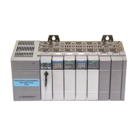
Provides instructions for installing the 1747-SDN module into the chassis and connecting it.
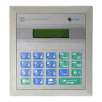
Guides the installation and DIP switch setting for the RediSTATION operator interface.
Explains how to connect and configure the Series 9000 photoeye to the network.
Shows a diagram of the fully installed example network configuration.
Provides steps for installing RSLinx and RSNetWorx for DeviceNet software.
Guides the user through configuring the DeviceNet driver using RSLinx software.
Explains how to set up an online connection and configure the 1747-SDN module's scanlist.
Details the procedure for setting or changing the node address of the 1747-SDN module.
Guides the configuration of I/O devices within the RSNetWorx software.
Instructs on verifying the I/O parameters for the photoeye device.
Guides the verification of I/O parameters for the RediSTATION operator interface.
Explains how to automatically map devices into the scanlist using RSNetWorx.
Details the process of downloading and saving the network configuration to the 1747-SDN module.
Lists the software and hardware requirements for using the pass-through feature.
Describes how to establish communication with DeviceNet over an Ethernet network.
Explains how to establish communication with DeviceNet over a Data Highway Plus network.
Steps for installing the necessary software (RSLogix 500) for the example program.
Guides the creation of a sample ladder logic program for testing the DeviceNet network.
Instructions for downloading and executing the example program via different network types.
Explains the meaning of the bicolor module status indicator and troubleshooting steps.
Describes the network status indicator and its role in diagnosing communication link issues.
Lists numeric codes displayed by the module for diagnostics and their meanings.
Introduces the DEM instruction for initiating generic CIP commands on DeviceNet.
Details the parameters required for setting up the DeviceNet Explicit Message instruction.
Introduces the AutoScan feature for automatic network device mapping.
Describes methods to set up and operate the AutoScan feature.
Illustrates a simplified, fixed map of discrete input data and status bits for DeviceNet devices.
Presents a simplified, fixed map of discrete outputs and data for DeviceNet devices.
Guides the configuration of M0 and M1 files using RSLogix 500 software's I/O Configuration.
Explains how to address and use the M0 and M1 data files in ladder programs.
Describes firmware enhancements, corrected anomalies, and important information for revisions.
Details firmware enhancements for revision 8.002, including EDS file and AutoScan.
Lists known anomalies found in firmware revisions 7.005 and 7.006.
Describes enhancements and corrected anomalies for firmware revision 6.002.
Details firmware enhancements, including explicit message pass-through and M1 file table.
Lists anomalies that have been corrected in firmware revisions.
Explains the four data areas used for information transfer between the module and processor.
Describes the mapping of input/output image tables and M1/M0 files for the 1747-SDN.
Details how the SLC processor reads input data from the module via image tables and M1 files.
Describes how the SLC processor writes output data to the module via image tables and M0 files.
Explains the feature's use in configuring device parameters and managing data exchange.
| Vendor | Allen-Bradley |
|---|---|
| Product Type | DeviceNet Scanner |
| Series | SLC 500 |
| Catalog Number | 1747-SDN |
| Communication Protocol | DeviceNet |
| Number of Nodes | 63 |
| DeviceNet Baud Rates | 125, 250, 500 kbps |
| Compatibility | SLC 500 series controllers |
| Input Data Size | 64 bytes |
| Output Data Size | 64 bytes |
| Operating Temperature | 0°C to 60°C (32°F to 140°F) |
| Storage Temperature | -40…85 °C (-40…185 °F) |
| Relative Humidity | 5% to 95% (non-condensing) |
| Input Voltage | 24V DC |