ControlLogix DeviceNet Scanner Module 23
Publication 1756-IN566B-EN-P - April 2001
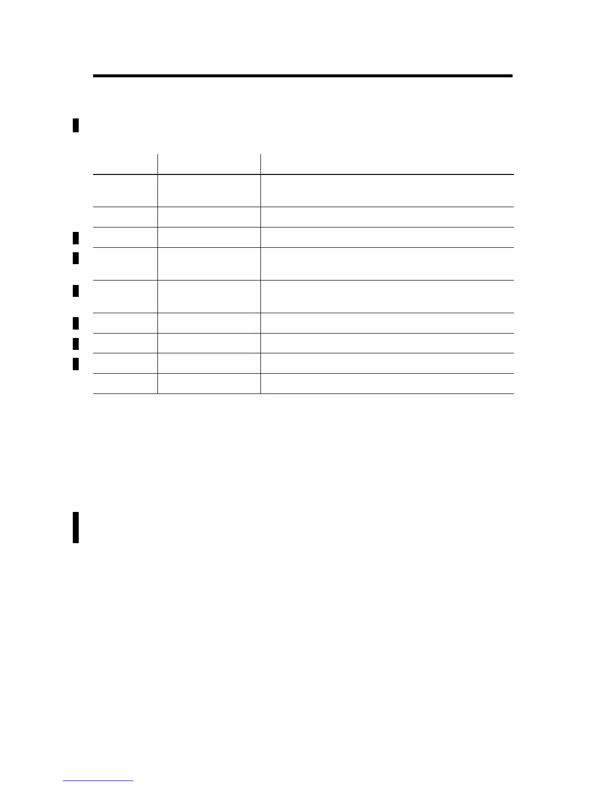
Module Status Register Bit Definitions
The bits of the Module Status Register are defined as follows:
Status Structure
The controller receives status information concerning the 1756-DNB
module’s ability to exchange DeviceNet messages with other nodes
by reading from the status structure in the 1756-DNB module. The
scanner module periodically updates the contents of the status
structure and copies its contents to the controller. The status structure
consists of several tables. The bit position of each of the 64 bits that
make up a given status table directly corresponds to the node address
of a device.
Bit Name Description
0 Run 1 = in run mode.
0 = in idle mode.
1 Fault 1 = network is faulted.
2 DisableNetwork 1 = network is disabled.
3 DeviceFailure 1 = device failure exists (examine the status structure
for causes).
4 AutoverifyFailure 1 = at least one device has failed to be initialized by
the scanner.
5 CommFailure 1 = communication failure exists.
6 DupNodeFail 1 = failure due to duplicate node address.
7 DnetPowerDetect 1 = DeviceNet power failure.
8 - 31 {Reserved}
unused
Allen-Bradley

 Loading...